This thread has been locked.

If you have a related question, please click the "Ask a related question" button in the top right corner. The newly created question will be automatically linked to this question.

TCAN1146-Q1: CAN Communication in Normal mode not working

Part Number: TCAN1146-Q1

Hello,

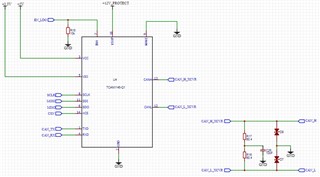
I am designing an electronic card based on an ESP32 and with a TCAN1146 as CAN transceiver to have the Partial Networking functionality.
I want to use Pin INH to activate the main power supply of my card from a CAN message to be configured in the TCAN1146.

The problem I'm having is that I can't send or receive CAN messages when the transceiver is in normal mode.

With a classic CAN transceiver I can send and receive CAN messages.
So I don't think I have any problem with the ESP32 firmware.

I have SPI communication working between the ESP32 and the TCAN1146. As well as the basic functions of writing and reading registers.

I tested the continuity on the CAN_RX / CAN_TX pins between the TCAN1146 and the ESP32 and the CAN_L / CAN_H continuity between the transceiver and the connector on my card.
There is no problem on that side either and I have 120 ohm between CAN_L and CAN_H.

At first, I do not activate the Selective Wake and I switch the tranceiver to normal mode by writing 0x07 in the MODE_CNTRL Register (Address = 10h).
By reading the register, I confirm that the transceiver is in normal mode, I recover the value 0x07 but the CAN communication does not work. CAN configuration is 500kbps in Standard Mode.

Am I forgetting a step in the configuration of the tranceiver to have CAN communication?

I put you below the values ​​of the relevant registers that I have.

INT_1 Register (Address = 51h) = 0x40 or 0x44 (CANINT and sometimes CANSLNT raised)
INT_2 Register (Address = 52h)  = 0x40 (PWRON raised)

Even if I clear the raised interrupts, the CAN communication still not work.

I've spent a lot of time trying to make this transceiver work.

The card must be produced in 3000 copies to start. If I can't unlock the use of this transceiver quickly, I will have to switch to a standard CAN transceiver.

I remain of course at your disposal and I thank you very much for the technical support that you can provide me.

Best,

Loïc FOLGOAS

  • Loïc,

    Thanks for the clear explanation here! Let me confirm a few things to see if we can track down what's going on:

    Apologies in advance for the many questions.

    Based on your description above, I am assuming that INH is properly high? And LIMP is low?

    Does RXD reflect the CAN bus if a differential dominant signal is applied externally?

    Do you observe CANH and CANL to be biased to 2.5 V, or are they biased close to GND?

    Best,

    Danny

  • Hi Danny,

    Thank you very much for considering my issue.

    I answer your questions below ;-)

    INH/LIMP

    DEVICE_CONFIG1 Register reading value is 0x00 meaning INH function is selected (INH_LIMP_SEL = 0)

    Then in Normal Mode I have 12V on INH/LIMP pin and 0V in Sleep Mode. Everything good I guess.

    RXD never reflects the CAN Bus, I always have 0V on RXD. If a differential dominant signal is applied externally from a CAN Bus device, I have 0V on RXD.

    I also applied manually from a power supply 3,5V on CAN_H and 1,5V on CAN_L to reproduce a differential dominant signal.

    I still have 0V on RXD but the strange thing is when I apllied those voltages, CAN_H is at 3,5V with 4mA of current and CAN_L is forced to 3V with 0mA (results displayed on the power supply).

    If I applied 2,5V on CAN_H and CAN_L, I have 0mA on CAN_H / CAN_L and 2,5V is well applied on both CAN_H / CAN_L.

    CAN_H and CAN_L are biased to 2,5V when no other device is connected on the CAN Bus as well as when there is a device connected.

    Finally, I shared the schematics of the TCAN1146 part of my ECU.

    Thank you very much for your support.

    Best,

    Loïc

  • Danny,

    I did further experiments with a standard transceiver board. When I applied manually from a power supply 3,5V on CAN_H and 1,5V on CAN_L to reproduce a differential dominant signal.

    Voltages on CAN_H stays at 3,5V and on CAN_L stays at 1,5V.

    So I decided to remove the ESD diodes on CAN_H and CAN_L just in case.

    No change, still not working.

    Best,

    Loïc

  • Loïc,

    Your observations seem to show that it's in Normal mode, so it should be passing TXD --> CAN and CAN --> RXD.

    You mention that RXD is 0 V when you are applying a differential signal on CANH/CANL. On its own, this is expected, since this dominant represents a logic 0 on RXD. However, have you confirmed that when CANH = CANL = 2.5 V, then RXD is simultaneously 0 V? This would be the unexpected behavior. I think you might have possibly implied this in your previous answer but I just want to confirm that you see RXD = 0 V when CANH = CANL.

    The main reason RXD would be latched low while CANH = CANL would be if you are in Standby mode after a BWRR (Figure 10-12), but if you have MODE_CNTRL = 0x07 then it should be in Normal mode.

    Have you also checked that there are also no additional interrupts on INT_3? (Not too worried about INT_CANBUS since you are driving signals on CAN externally)

    It is expected to have some current flowing from the CANH connection since you have the termination applied between CANH and CANL, so this is not odd to me.

    Do you by chance have any measurement of the current into VSUP (or maybe VCC)? We would expect ISUP > 95 μA in this mode.

    Best,

    Danny

  • Danny,

    When I apply 2,5V on CAN_H and CAN_L, I have 0V on RXD.

    INT_3 equals 0x00.

    I don't have the possibilty to measure the current on the TCAN on my board. Supply of the TCAN is directly connected to power and ground through vias to go to inner layers.

    Best,

    Loïc

  • Loic,

    Thanks for the information, we'll have a response to you by Monday end of business CST.

    Regards,

    Eric Hackett

  • Hi Loic,

    Have you been able to verify that the CAN transmitter is working correctly? If you drive a dominant (low) on TXD, does the CAN bus move to a dominant state? This would help us verify if the device is being properly supplied. Please also confirm the voltages present at the Vcc and Vio supplies are within the expected range. Please measure the conditions as close to the IC pin as possible. 

    Have you observed this behavior with multiple TCAN1146 units? I would recommend replacing the device with a new unit to ensure this behavior is not a result of a damaged device. 

    Does the device behave any differently when placed into listen mode (MODE_CNTRL = 0x05)? I'm wondering if anything from the CAN driver being active is related to this issue. 

    Regards,
    Eric Schott 

  • Hello,

    Sorry for my late reply, I took the time to wire another card.

    After mounting it, everything now works fine.

    I can send and receive CAN messages with the ESP32.
    I also have partial networking working.

    For the moment any CAN frame wakes up the transceiver but I have enough on the datasheet to move forward on this.

    Thank you for your support, the problem must have come from a bad wiring of the previous card.

    Best,

    Loïc

  • Last,

    As the supply of the component seems to be tricky, would you please share me a contact from sales ?

    Cards will now be produced soon with a french EMS for 3000 units.

    Again thank you for your support.

    Best,

    Loïc

  • Hi Loic,

    I'm glad to hear that you are able to send and receive CAN data. Let us know if we can help at all with the partial networking configuration. 

    Are you currently in contact with a Field Applications Engineer from TI? They will be best at connecting you with our internal teams to discuss supply and pricing. What package option are you planning to use for this design?

    Regards,
    Eric Schott