This thread has been locked.

If you have a related question, please click the "Ask a related question" button in the top right corner. The newly created question will be automatically linked to this question.

THVD1424: Resistance for TX and RX

Part Number: THVD1424

Hello team,

I received questions from the customer.

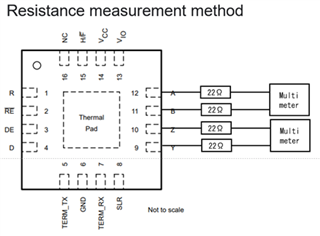
Under the following conditions, only the highlighted area has a high resistance value, is this a problem? Communication is working even if the resistance is high.

Half / Full duplex Termination resistance configuration TX(pair) RX(pair)
Full TX: ON, RX: ON 10.18M ohm 160.9 ohm
Full TX: OFF, RX: OFF 16.67M ohm 124.3k ohm
Half TX: ON, RX: OFF 160.7 ohm 298.6k ohm
Half TX: OFF, RX: OFF 109.5k ohm 298.5k ohm

Regards,

Masa

  • Does "pair" mean that you are measuring between the two bus pins? A differential transmitter drives the bus by connecting one output pin to VCC and the other one to GND. So there is no connection between these pins inside the transmitter.

    If there are any termination resistors (inside the transceiver, or external), you should be able to measure them. So it appears that the configuration is not what you think it is.

  • Hi Masa,

    What pins are you measuring the resistance from on the TX and RX pairs? 

    What is the supply voltage you are using, what is the logic voltage supply, and what voltage is applied to the termination pins? 

    Termination should be typically 120 when the integrated resistor is applied (so the 160 ohms seems to show that the termination is active) 

    Do you have the termination set through a pull-up or pull-down or are you changing the termination status while the device is operational? The device is meant to be configured at start-up and features should be set at start-up  - if changing during operation you may not get the expected results. 

    The device can communicate without proper termination - the issue is reflections - if a bus is long enough relative to the frequency of the data signal  - without proper termination you can get large signal reflections that will degrade signal integrity and could result in failed communication. In shorter bus applications terminations are not necessary as reflections are negligible.  What constitutes a short bus is dependent on signal wavelength - you don't need to account for potential reflections if the electrical length of the bus is less than 1/10th of the wavelength  - for a pulse train like RS-485 it is going to be the wavelength of the fundamental frequency, harmonics wavelength, and also you need to also consider the rise/fall time (as this is a trapezoidal pulse train as there is a defined slope from low to high value and vice versa). So it depends on system setup if you need termination - but in most applications for RS-485 you will have termination resistors 

    Please let me know on the questions I asked so I can verify test setup to ensure it is being done correctly with respect to the device.  

    Best,

    Parker Dodson

  • Hello Parker,

    Thanks to the support.

    What pins are you measuring the resistance from on the TX and RX pairs? 

    The customer has measured pins 11 and 12 for RX and pins 9 and 10 for TX.
    For any other questions you may have, we will check with the customer.

    Regards,

    Masa

  • Hi Masa,

    1. Is there anything else connected to the pins when measuring the resistance? 

    And a few questions from my last post that would be helpful in identifying an issue.

    2.. What VCC and VIO levels are being used in the system.

    3. What voltage level is applied to the TERM logic pins?

    4. Is the customer changing the termination while the device is operational - i.e. do they turn on the device and then apply a logic signal to the TERM pins? 

    Please let me know.

  • Hi Parker,

    Thank you for your investigation.
    Sorry for the late reply.

    1. Is there anything else connected to the pins when measuring the resistance?
    A. Two of 22Ω resistances are connected in series.

    2.. What VCC and VIO levels are being used in the system.
    A.3.3V is applied to Vcc and Vio pins.
    3. What voltage level is applied to the TERM logic pins?
    A. 3.3V or 0V is applied to the TERM pins according to the command.
    4. Is the customer changing the termination while the device is operational - i.e. do they turn on the device and then apply a logic signal to the TERM pins?
    A. Yes, Voltage is applied to the TERM pins after both Vcc and Vio are powered on.

    Thank you in advance for detail information according to our answer.

    Regards,

    Nao

  • Hi Nao,

    Thanks for the detailed reply I appreciate it!

    So if possible - I would like you to run the test again - but set it up slightly different. 

    Can you attach a pull-up resistor - like 4.7k to 10k from VIO to the TERM pins or if that test is hard in the current system - can you direct connect VIO to the TERM pins, then power up the device, then measure the impedance in full duplex mode to see if the resistance value is more in line to what you expected. The device isn't designed to have the TERM pins changed on the fly - and I think that could be part of the issue why the resistance measurements you are getting are higher than expected. 

    Please let me know what the results are after this test so I can verify if this is the actual issue.

    Best,

    Parker Dodson