This thread has been locked.

If you have a related question, please click the "Ask a related question" button in the top right corner. The newly created question will be automatically linked to this question.

TCAN4550EVM: tcan4x5x Driver Loading Issue

Part Number: TCAN4550EVM
Other Parts Discussed in Thread: TCAN4550

Hi TI Team,

We are using TCAN4550 EVM with IMX8MN Nano EVK.

We are loading 3 drivers for TCAN4550 module.

1)insmod can-dev.ko

2)insmod m_can.ko

3)insmod tcan4x5x.ko


It is showing below mentioned error during tcan4x5x driver loading.

[   35.106793] tcan4x5x spi1.0: no clock found

[   35.111038] tcan4x5x spi1.0: no CAN clock source defined

[   35.177749] tcan4x5x spi1.0: Unsupported version number:  0

[   35.214917] tcan4x5x: probe of spi1.0 failed with error -22

Could you please guide us for unsupported version number issue.

Note – For TCAN EVM we are not providing clock. TCAN EVM has itself 40 MHz crystal clock.


Reference log


1) root@CT-100:~#

root@CT-100:~# insmod can-dev.ko

[   22.982106] CAN device driver interface

root@CT-100:~#

root@CT-100:~# insmod m_can.ko

root@CT-100:~#

root@CT-100:~#

root@CT-100:~# insmod tcan4x5x.ko

[   35.106793] tcan4x5x spi1.0: no clock found

[   35.111038] tcan4x5x spi1.0: no CAN clock source defined

[   35.177749] tcan4x5x spi1.0: Unsupported version number:  0

[   35.214917] tcan4x5x: probe of spi1.0 failed with error -22


We are using below mentioned pins for hardware connection between TACN EVM and IMX8 Nano.

1)SDI
2)SDO
3)SCLK
4)RST
5)GPO1 / CLKOUT
6)nCS
7)nINT
8)GPO2

If any additional details are required, please let me know.


Regards

Ramji Mishra

  • Hello Ramji,

    The Unsupported version number: 0, and the -22 error, are likely from a bad SPI configuration, or a SPI protocol error that is preventing successful communication with the TCAn4550 registers. 

    Can you check to see if the SPI bus is configured and initialized properly, and also monitor the waveforms with a scope or logic analyzer to see if they are correct?  If so, can you provide those waveforms for my review?

    One common issue is that the TCAN4550 requires 32 bit words and many SPI modules may not be setup to support that without some modification.  We need to make sure the SPI configuration is correct and able to communicate with the TCAN4550.

    Regards,

    Jonathan

  • Hi Jonathan,

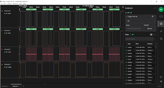
    Thanks for your response. I tested  SPI communication. spidev.ko driver and spi-test utility were used for testing. No slave device was connected on the SPI bus. External loopback connector was used for data transfer between MISO and MOSI line.

    Please find the below attached logic analyzer waveform.

    Please confirm it/suggest any other test topology.

    Regards

    Ramji Mishra

  • Hi Jonathan,

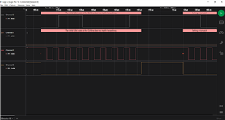
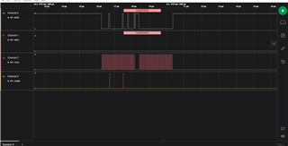
    I have also tested SPI signals with TCAN module. Signals were captured when tcan driver was loading. It is showing the initial (idle) state of the clk line does not match the settings in MISO and MOSI Line. Please find the below attached logic analyzer waveform.

    TCAN4550 requires 32 bit words and many SPI modules- Please guide me where i can check this 32 bit words settings.

    Regards

    Ramji Mishra

  • Hi Ramji,

    The initial idle state of the clock (polarity) is in fact different than that expected by the TCAN4550. 

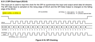
    I am not familiar with the specific processor or the SPI drivers it has, so I can only support this issue from pointing out the requirements of the TCAN4550.  Many SPI drivers support different SPI modes, or polarities between the clock and data signals.  These are usually easily changed with a parameter setting in the function call.  If the SPI driver has a mode control parameter, it should be set to "MODE 0 (CPOL=0, CPHA = 0).

    But also more importantly, the Chip Select or "Enable" signal is toggling High after every 8 bits.  This is incorrect, and the Chip Select or Enable signal must remain LOW for ALL bits in the SPI transaction.  Once the enable signal goes HIGH, the TCAN4550 terminates the SPI transaction and checks for an error condition by determining if it received the correct number of bits which must be a multiple of 32 (or one complete word of data) as well as whether it received enough Words of data based on the "Length" field in the SPI header, or the 4th byte sent following the Chip Select or Enable signal transitioning LOW.  If the bits received was not a multiple of 32 bits, or had too many or too few data words, then the device will throw a SPI Error and discard any data received in the transaction.  This is likely what is happening in the customer's application.

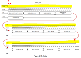
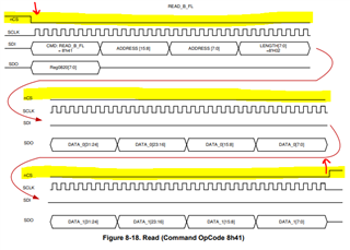
    You can see in the datasheet timing diagrams for a SPI Write and SPI Read transaction that the Chip Select (nCS) or Enable signal transitions LOW at the beginning of the transaction and remains LOW for a minimum of 2 words or 64 bits or SPI Clock Cycles.  The diagrams actually shows that two consecutive registers are written by setting the Length field to "2" and therefore there are 96 SPI clock cycles while the Chip Select signal is LOW.  However, for single register Read or Write, there should be at least 64 bits or SPI Clock Cycles while the chip select is LOW.  The first 32 bits are the R/W Op Code (0x41 or 0x1), followed by the register address, and then the Length field to indicate the number of registers or words of data that will follow.  For a single register R/W, the Length Field should be set to "1".  Following this first 32 bit "header" word, there should be 32 bits of additional data transmitted for each register or word of data indicated by the Length byte.

    Therefore, the SPI driver may need to be modified to support both a 32 bit word of data (currently it is set to 8 bits) and it needs to keep the Chip Select or Enable signal LOW between the 32 bit words so that the R/W transaction won't be aborted immediately after the Header word (or first 32 bits) have been transmitted.

    Resolving the SPI Mode or Clock/Data polarity and modifying the SPI driver to correct the Chip Select transitions should allow the processor to communicate with the TCAN4550 and resolve this issue.

    Regards,

    Jonathan

  • Hi Jonathan,

    Sorry for late reply. I made below changes in  TCAN driver.

    static int tcan4x5x_can_probe(struct spi_device *spi)
    spi_set_drvdata(spi, priv);

    /* Configure the SPI bus */
    - spi->bits_per_word = 8;
    + spi->bits_per_word = 32;
    + spi->chip_select = 0;
    + spi->mode = SPI_MODE_0;
    + printk("******SPI-MODE=%d\n******",spi->mode);
    + printk("******BIT-PER-WORD=%d\n******",spi->bits_per_word);
    ret = spi_setup(spi);
    + printk("******SPI-SETUP-RET=%d\n******",ret);
    if (ret)

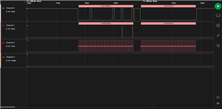
    I am able to see 32 bit per word and configured chip select as gpio. chip select is now low but still i am not able to read the version number.

    It is showing below mentioned data and clock in logic analyzer.

    After some time TCAN is going to sleep mode/ any other mode. I am seeing below mentioned output in logic analyzer.

    I want to know about 0x01000841 and 0x00000000 data.

    Regards

    Ramji Mishra

  • Hi Ramji,

    The Chip Select pin must transition from a High to a Low to signal the Start of a new SPI write or read transaction and it must transition back to high at the end of the transaction to signal the SPI transaction is complete.  The TCAN4550 will count the clock cycles between the chip enable transitions to ensure there are exactly the correct number otherwise it will treat this as a SPI Error.

    It also looks like your byte sequence is reversed.  For example in a read, the most significant byte that is sent is 0x41.  Your second plot shows that the 0x41 is the least significant byte sent in the first word.

    Can you make sure the GPIO connected to the chip enable is transitioning from high to low at the start and then low to high at the end of each SPI transaction and then also make sure the byte order is correct?  Once you get the chip select working, the TCAN4550 should start sending you the status byte on the MISO line even if you have your byte polarity incorrect.

    Regards,

    Jonathan