This thread has been locked.

If you have a related question, please click the "Ask a related question" button in the top right corner. The newly created question will be automatically linked to this question.

TCA9535: Could TCA9535 be used to simulate PWM output?

Part Number: TCA9535

Hi team,

     The customer is evaluating the TCA9535. Here is how they use: They use TCA9535 to simulate six channel  pwm at 1KHz to drive 2 RGB leds.

     Could you please confirm that:

     Q1 When simulating 1KHz pwm output, how fast does TCA9535 change the Low to High with I2C clock at 100KHz and 400KHz respectively? 

     Q2 As mentioned before, they need six channels to drive leds.Customers can invert one I/O via I2C and they want to know how long it takes to invert all 6 I/O with I2C.

YOURS

NAN

  • NAN,

    Q1 When simulating 1KHz pwm output, how fast does TCA9535 change the Low to High with I2C clock at 100KHz and 400KHz respectively? 

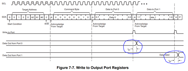
    I think Q1 is referring to the tpv timing parameter which is the output data valid for various supply voltages. 

    As you can see from the timing spec and the signal diagram, tpv is the time between the rising edge of the ACK (9th clock cycle) and the time where data on the output port register changes. TCA9535 and the rest of our IO expanders changes the states of a p-port only on the rising edge of an ACK bit. This means that 9 clock pulses must cycle before the state on a GPIO changes. 

    If you are talking about the time from the rising edge of the ACK bit and when the output port changes state, the maximum time is 200ns for the VCC range 2.3V < VCC < 5.5V, or 300ns for the VCC range 1.65V < VCC < 2.3 V. 

    If you are talking about transition from LOW to HIGH from when you first see the output change, then you would have to wait a total of 9 clock cycles before data can be changed from LOW to HIGH since data inside a port register is only changed on the rising edge of an ACK. 

    This means,

    100k: 1 clock = 10us, 9 clocks = 90 us between each state change

    400k: 1 clock = 2.5us, 9 clocks = 22.5 us between each state change

    Q2 As mentioned before, they need six channels to drive leds.Customers can invert one I/O via I2C and they want to know how long it takes to invert all 6 I/O with I2C.

    Just as a precautionary question, how many LED's will be on at a single given time, and how much current does each LED draw? The abs. max rating for the TCA9535 has a continuous current through VCC limit of 160 mA. 

    I think I answered this Q2 question in Q1 answer. The output state changes for a port (P0.0 - P0.7 or P1.0 - P1.7) only after the 9th clock cycle which is the ACK bit. 

    Regards,

    Tyler