This thread has been locked.

If you have a related question, please click the "Ask a related question" button in the top right corner. The newly created question will be automatically linked to this question.

DS90UB948-Q1: Interface forum

Part Number: DS90UB948-Q1

Hello,

Problem description: We use a product of the deserializer DS90UB948-Q1. When the customer uses it, the picture flickers.

When the problem occurs, by reading and printing the value of the 948 register, compared with the normal 948 register value,

only the register value of the address 0xA2 has changed, from 8c to 7d.

Screenshot of normal value:
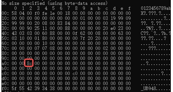
1.Why can't I find this register 0xA2 in the specification? 

2.What does the change of this value mean?

3.Could the accidental phenomenon in the figure below be possible that the signal is interfered,Can it be solved if the output voltage swing is increased?

Output voltage swing configuration register 0x4B is 0

Best regards

Kailyn

  • Hi Kailyn,

    1. How many ICs and Systems do you see this failure on?
    2. What is the expected value you are seeing for 0xA2 on a good vs. bad system?
    3. Have you done ABA swap to the suspect IC and does the failure follow the IC from a known good system to another system and vise-versa?
    4. What is the lock status while the screen is flickering?
    5. Does the screen actually flicker or is it just an offset of colors ?
    6. Have you done any MAP analysis to test the link margin of your system?
    7. VOD 0x4B = 0x0 is low the default value should be 0x8 
    8. When you see the flickering screen does the lock signal flicker as well?

    Regards,
    Fadi A.

  • Hi Fadi,

    Thank you for your reply, some questions I have confirmed with the customer.

    What is the expected value you are seeing for 0xA2 on a good vs. bad system?

    The 0xA2 value:

    good: 0x8C

    bad:0x7d

    What is the lock status while the screen is flickering?

    After the screen flicker problem occurs, it cannot be restored to normal. It needs to be powered on again to restore normal. Reading the register value LOCK is normal. The probability of this problem is very small and this phenomenon cannot be reproduced on the desktop

    Have you done any MAP analysis to test the link margin of your system?

    No, he didn't do the MAP analysis, he wants to know register 0xA2 meaning.

    In addition, he found that  when the interference is removed, it can return to normal.The image flickering phenomenon on the vehicle cannot be self recovered, and the system needs to be restarted to recover.

    .D2+/-transfer HS SYNC,VS SYNC and data DE, If the oscilloscope probe is not connected to the signal line, interference with the interphone will not flicker. When the interference is removed, it can return to normal. It looks like one of the serializer output or 948 output, and TFT LCD display terminals is abnormal.

    Best regards

    Kailyn

  • Hey Kailyn,

    • How many failures are you seeing with this failure?
    • Have you tried doing ABA Swap?
    • Does the failure follow the 948 IC ?

    0xA2 is a reserved register. We use it to set the internal always-On CLK (AON) to a specific range.
    This should not effect video performance. Basically, regardless of register 0xA2 value, if your system uses an external CLK, then AON value doesn't matter, it should be irrelevant to the video performance since your video is driven by an external CLK source. 

    If this issue is only happening on a single IC can you please do ABA swap to see if the issue follow the suspect IC when putting it on a known good system and vise-versa ? If yes, we can help you send it to quality for IC level testing. 

    Regards,
    Fadi A.

  • Hi Fadi,

    Thank you very much for your reply, and below is the customer's feedback.

    1.There are three systems have this failure had  occurred.

    2.The suspicious IC has not been swapped yet, which is a very unlikely fault phenomenon, even if swapping is difficult to replicate during testing on the desktop.

    3.there is only screen flickering and no offset of colors.

    4.The output voltage swing (differential)Vodp-p setting is generally 350mV,I need to check the register values with my colleagues.

    5.The faults were all caused by the complete product installed on the vehicle, and there was no test lock signal, so it is not known. If there is any jitter in the signal when tested on the countertop late. 

    Best regards

    kailyn

  • Hi Kailyn,

    Sorry for the delay. 

    1.There are three systems have this failure had  occurred.

    you have 3 systems failing out of how many already built ?

    2.The suspicious IC has not been swapped yet, which is a very unlikely fault phenomenon, even if swapping is difficult to replicate during testing on the desktop.

    Can you please clarify what this means? The idea here is to replace the suspect 948 IC with a different 948 IC that is considered a "good" IC to see if the failure mode recovers and on the other hand place the suspect 948 IC on a known good system board to see if the failure mode follows the suspect 948  IC on the good system.

    5.The faults were all caused by the complete product installed on the vehicle, and there was no test lock signal, so it is not known. If there is any jitter in the signal when tested on the countertop late. 

    Is this issue still ongoing or has it been resolved with the input provided?

    Regards,
    Fadi A.