This thread has been locked.

If you have a related question, please click the "Ask a related question" button in the top right corner. The newly created question will be automatically linked to this question.

DP83869HM: Setting difference between Rev A and Rev B

Part Number: DP83869HM
Other Parts Discussed in Thread: DP83869

Hello,

I would like to confirm difference between Rev A and Rev B of DP83869HM.
I understand that difference between these two is below.

* change design to fix occasional anomaly in fiber auto negtiation.

This means I understood TI only changed point which is related to fiber auto negotiation.
However, I found following difference.

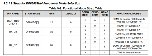
1. Setting for "RGMII to 1000Base-X" is changed.
According to datasheet Rev B, there is following description on "RGMII-to-1000Base-X Mode".

• Write 0x0041 to register 1DFh // Set Operation Mode to RGMII to 1000Base-X
• Write 0x1140 to register C00h // Reset FX_CTRL
• Write 0x4000 to register 1Fh// Software Reset

On the other hands, in case of datasheet Rev A, there is following description on "RGMII-to-1000Base-X Mode".

After configuring register 0x01DF, perform the following operations.
• Write 0x1140 to register 0x0000

The register access is added in Rev B.
And register which TI require to write 0x1140 is changed from 0x0000 to 0xC00.

2. Address 0x1EC, 0xC09 and 0xC10 are disclosed at datasheet Rev B.

Then I have following questions.

Q1. Even if user use Rev A version of DP83869HM device, do user need to follow description of datasheet Rev B when they use "RGMII to 1000Base-X" mode ?
Q2. If user use Rev A version of DP83869HM device, can user also access registers which I described above "2" ?
Is it added on Rev B version of DP83869HM only or TI just mistake datasheet Rev A description (just change typo) ?

Best Regards,

  • Hello,

    Regarding your first question, if you check closely, Rev A datasheet tells to give the appropriate op-code prior to its explicit commands. Instead now, this op code is now explicitly defined for all of the modes, Reg 0x1DF. The methodology is the exact same regardless of revision.

    Regarding your second question, these were made public to correct typo in Rev A. This has same functionality between device revisions.

    Sincerely,

    Gerome

  • Hello,

    I understood about answer of Q2.
    I have other questions for answer of Q1.

    1-1.
    >Instead now, this op code is now explicitly defined for all of the modes, Reg 0x1DF.
    I understand answer of above, however, I have following question.

    According to datasheet of Rev A, TI described that user need to write 0x1140 to Address 0x0000.
    On the other hand, according to datasheet of Rev B, TI described that user need to write 0x1140 to Address 0x0C00.

    My customer said that when write data to address 0x0000, it seems that same data will be applied to address 0x0C00 in case of using DP83869HM with rev A.
    (Vice versa.)

    However, TI changed description about register which 0x1140 should be writtern when TI changed datasheet from Rev A to Rev B.

    Q1-1-1. In case of Rev A, is 0x0C00 shadow register of 0x0000 and changed treatment of this register when you update Rev B ?
    (In case of Rev B, 0x0C00 is not shadow registert of 0x0000 ?)
    Q1-1-2. If answer of above Q1-1-1 is "NO", could you please tell me how user distinglish standard register (0x0000) and extension(vendor define) register (0x0C00) ?
    (Because, if user set address 0x0000 to something, same setting will be applied. in other words, I think user do not need to access extension(vendor define) register.)

    Best Regards,

  • Hello,

    I am not familiar with your terminology "shadow register". For Rev A datasheet, this is a typo that was corrected. It should be 0x1140 written to Reg 0xC00. This methodology would need to be followed regardless of silicon revision. 

    Sincerely,

    Gerome

  • Hello,

    Thank you for your reply.
    I'm not sure whether 0xC00 is working as shadow register but I think behabior is similar so I wrote it.
    Here is explanation about shadow register.

    Simply put, shadow register is a register devised within the microcontroller for purpose of holding certain data to be used later. The name "Shadow" implies to duplicate some value and use it again - so it wont get lost.
    https://electronics.stackexchange.com/questions/86032/what-actually-is-a-shadow-register

    By the way, what do you think about following behavior ?

    >My customer said that when write data to address 0x0000, it seems that same data will be applied to address 0x0C00 in case of using DP83869HM with rev A.
    (Vice versa.)

    From above, we have following question.

    How do user distinglish standard register (0x0000) and extension(vendor define) register (0x0C00) ?
    (Because, if user set address 0x0000 to something, same setting will be applied. in other words, I think user do not need to access extension(vendor define) register.)

    Best Regards,

  • Hello,

    Thank you for your query. To access registers outside 0x0 - 0x1F but within the MMID 1F space, please see section 9.4.9.1 of datasheet. All customer needs to do is a 4 step register write process to write a non-0x0 through 0x1F register.

    Sincerely,

    Gerome

  • Hello,

    Thank you for your reply.
    I understand about section 9.4.9.1.
    In other words, I understand address 0x0 and 0xC00 is not connected(related) from above section.
    (If user want to access address 0x0, they just point out 0x0. And if user want to access address 0xc00, user need to set REGCR[4:0] and set ADDAR to point out 0xc00. Therefore access method is different.)

    However, customer said as shown below.

    >My customer said that when write data to address 0x0000, it seems that same data will be applied to address 0x0C00 in case of using DP83869HM with rev A.

    (Vice versa.)

    Could you re-confirm whether standard register (0x0 - 0x1F) is NOT related to extended register of related to fiber (register name is FX_xxx and Add 0xC00 to 0xC19) internally ?

    Best Regards,

  • Hello,

    While it does appear that same data is set between 0x0 and 0xC00, these are independent registers from each other and must be set independently.

    Sincerely,

    Gerome

  • Hello,
    >While it does appear that same data is set between 0x0 and 0xC00, these are independent registers from each other and must be set independently.
    I recognize about above.
    However, in fact customer said when they just set data to address 0x00, same data is applied to address 0xC00 as well.
    So, this means when user set data which they want to write to address 0xC00, if something set data to address 0x0 after that, data of address 0xC00 is overwritten unintentionally. 
    Could you understand our situation ?

    Best Regards,

  • Hello,

    I think I now understand the context, but I disagree with the findings. I just tested on DP83869 EVM with USB2MDIO. I first read 0x0 and 0xC and they read out 0x1140 and 0x140, respectively. I then change register 0x0 to have 0x900, read back to confirm, and then read 0xC. That value does not change.

    Sincerely,

    Gerome

  • Hello,

    >I then change register 0x0 to have 0x900, read back to confirm, and then read 0xC. That value does not change.
    Good. I also expected this result. they are using Linux OS and use linux device driver.
    So, I think something wrong operation is performed on this driver. I will ask customer again.

    BTW, they are refering following driver information. But it seems that this driver only apply rev 1 (value of 0x03 is 0xa0f1).
    https://git.kernel.org/pub/scm/linux/kernel/git/torvalds/linux.git/tree/drivers/net/phy/dp83869.c

    #define DP83869_PHY_ID 0x2000a0f1

    Do you have plan to change device driver ? Or should customer response new revision by changing driver code themselves (commit by TI or customer ?)?

    Best regards,

  • Hello,

    The fix on the driver should be that there should be another #define which has the new PHY ID, 0x2000A0F3, and wherever there is a conditional referencing DP83869_PHY_ID, there should be a OR operation between the old and new device ID's. 

    Sincerely,

    Gerome

  • Hello,

    I'm sorry let me re-confirm about below.

     I first read 0x0 and 0xC and they read out 0x1140 and 0x140, respectively. I then change register 0x0 to have 0x900, read back to confirm, and then read 0xC.

    Is above "0xC" mistake of "0xC00" ?
    (Actually, there is no disclosed register about address "0xC", so I believe that this is mistake of "0xC00".) 

    And also, I would like you to confirm functional mode of EVM.
    If your EVM setting is different from "RGMII to 1000Base-X", could you please confirm result after changing strap pin to "001" ?


    Best Regards,

  • Hi Machida,

    Yes, 0xC should be 0xC00. And yes, pin 22 should be pulled high while pins 36 and 35 can be left without strap or be pulled down.

    Sincerely,

    Gerome

  • Hello,

    Thank you for your reply.
    So, did you confirm that address 0x1df show 0x41, right ? 
    (I wonder why 0xC00 shows 0x140 on your previous thread. Because default value both address 0x0000 and 0xC00 is same value 0x1140.)
    I think that customers phenomenon may happen only when this device is set as "1000Base-X" fiber mode.
    So, I asked this.

    Best Regards,

  • Hello,

    I will need to check this in lab. Please expect a response by next Wednesday at latest.

    Sincerely,

    Gerome

  • Hello,

    When strapped into RGMII to 1G Fiber, Register 0x1DF shows 0x0001. Upon further review, it has been determined that [6] is not relevant to device function for this mode. We will look to correct this in next datasheet revision. 

    While strapped into this mode, 0xC00 read out 0x1140.

    Sincerely,

    Gerome

  • Hello,

    Thank you for your confirmation.
    -1-
    >While strapped into this mode, 0xC00 read out 0x1140.
    How about result of following procedure which you posted during above condition ?

    I just tested on DP83869 EVM with USB2MDIO. I first read 0x0 and 0xC and they read out 0x1140 and 0x140, respectively. I then change register 0x0 to have 0x900, read back to confirm, and then read 0xC. That value does not change.

    -2-
    >Upon further review, it has been determined that [6] is not relevant to device function for this mode.
    According to datasheet of rev B, TI described user need to write 0x41 to Address 0x1DF in section 9.4.8.2 RGMII-to-1000Base-X Mode.
    However, do you mean that user do not need to write "1" to bit[6] of address 0x1DF ?

    Best Regards,

  • Hello,

    The above state described in -1- was when PHY was in RGMII to Copper mode, Op Code 0. These registers are independent of each other and please treat them as such.

    For -2-, this is correct. This bit will not be relevant for this mode.

    Sincerely,

    Gerome

  • Hello,

    >The above state described in -1- was when PHY was in RGMII to Copper mode, Op Code 0. These registers are independent of each other and please treat them as such.

    What I want you to ask is when you set Op code 1 (RGMII to 1000Base-X), you can observe same result as case of Op code 0 or not.
    could you give me reply for above ?

    BR,

  • Hello,

    When in Op Code 1, Reg 0xC00 = 0x1140 by default. However, when changing Reg 0x0 to 0x900 as before, it is observed that Reg 0xC00 reads back 0x900 as well.

    Sincerely,

    Gerome

  • Hello,

    Thank you for your confirmation.
    I understood that you got same result which I posted (Customer obeserved).

    Then, I have following question.

    Q. When user use RGMII to 1000Base-X mode, how user treat standard register ?
    Do you recommend only to control extention register ?

    According to datasheet 9.4.8.2, it seems that TI recommend to control extention register.
    However, from above, since extention register is changed just controling standard register, user just control standard register in case of RGMII to 1000Base-X mode ?

    Best Regards,

  • Hello,

    When in RGMII to 1000Base-X mode, please access register 0xC00 for appropriate register control.

    Sincerely,

    Gerome