This thread has been locked.

If you have a related question, please click the "Ask a related question" button in the top right corner. The newly created question will be automatically linked to this question.

SN65LVDS100: SN65LVDS100 exist the problem of resistance breaking and lead to can’t output PG signal.

Part Number: SN65LVDS100

Hi team,


Customer feedback the LVDS application circuit exist the problem of resistance breaking and lead to can’t output PG signal.

Details are in the attachment, can you give some suggestions about it?

Attached information is my translation,LVDS信号产品电阻断裂PG无法检出.docx if there is any problem, please contact me

  • Hi,

    The LVDS driver has a 3.5mA current source. On the other side, the receiver input is very high impedance, so virtually all the current flows through the 100ohm termination resistor. This generates the differential voltage of 350mV across the receiver input. If the 100ohm termination resistor is broken or damaged, then you will not see the proper signal. 

    Thanks

    David

  • Hi David,

    We think this should be the case, so the first reaction when we got the fault phenomenon for the first time was that the output resistance of br401 caused the signal end resistance to break and could not reflect the abnormality.
    Therefore, we choose a new chip that does not have a built-in 100 ohm resistor at the output end, and the test phenomenon is still the same after the board is back.
    I just want to know why has shown the effect of the two chips in this situation. Specifically, I has provided br401 and br401+ new products. The solution, the new solution, and the results under the three conditions may not only be a question of whether the output has a built-in 100-ohm resistor, but may also be related to the internal composition of chip. Please give an in-depth answer.

  • Hi,

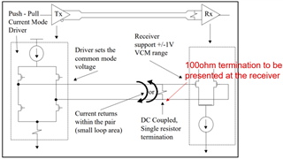
    Please see the block diagram below

    LVDS is a push-pull current mode driver. Even with an internal 100ohm termination at the BR401 output, we are still expecting to see a 100ohm single resistor at the LCD panel receiver (red color in the block diagram). With a 3.5mA current source flow through the 100ohm resistor, it will generate the differential voltage of 350mV, (3.5mA * 100ohm).

    My understanding from reading their problem description is that the 100ohm termination at the LCD panel receiver is broken so they are not seeing the right waveform on the scope, is my understanding correct? If this is the case, then they would need to fix the 100ohm termination at the LCD panel.

    Thanks

    David