This thread has been locked.

If you have a related question, please click the "Ask a related question" button in the top right corner. The newly created question will be automatically linked to this question.

DP83TG720S-Q1: Driver code for T1 PHY

Part Number: DP83TG720S-Q1
Other Parts Discussed in Thread: USB-2-MDIO

Hello Team,

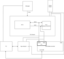
We are working on enabling the TI PHY module for 1000Base-T1 in our ECU board, for a customer requirement. We have managed to establish writing and reading of the registers from the MAC(MCU) to PHY. Now we are further developing the PHY. Do you have any driver codes or packages for this T1 PHY chip? I checked in the forums, but only found the linux version with one c file available.

Thanks in advance.

Aarathi Thomas

  • Hi Aarathi,

    We only have the Linux driver available, which you have found. Unfortunately we do not have anything further to provide.

    Thanks,

    David

  • Hi David,

    Thank you for the input. 

    I have another query. We have purchased a DP83TG720 G-Bit Media Converter, and this comes with a pre-programmed MSP40F5528 and two PHYs with specific PHY ids. 

    Is it possible to access another DP83TG720-Q1 PHY(register access) located on another board(an ECU board for example), when the MDIO and MDC is connected to the MDIO and MDC of this DP83TG720 G-Bit Media Converter since there is an MSP430. Or is the MSP430 Launchpad required ?

    Using the USB-2-MDIO tool, and clicking on the Find PHY ID option, we were able to see that the Media converter board was showing available for PHY ID 0x00 and 0x08 which are the phy ids for the two PHYs located on the same board. But when performing the setup mentioned above paragraph, we could see 'not available' for the PHY id of the PHY located on another board. Though the PHY is functioning and we are able to access the registers via MCU on the same board(ECU board)

    This experiment was to confirm whether we can use the DP83TG720 G-Bit Media Converter to set registers on external PHYs. Please let us know if you have any input on this.

    Thanks in advance 

    Aarathi

  • Hi Aarathi,

    This should be possible if MDC and MDIO is connected to PHY on another board. The PHY on that board should be powered up prior to powering on the DP83TG720 media converter. If the reverse power sequence is followed, I do not expect the other PHY to be recognized. Please let me know which order you have powered the boards in. Please also make sure a common ground is connected between the media converter board and the other PHY.

    Thanks,

    David

  • Hi David,

    Thank you for the quick response. We initially had done the reverse power sequence. Using the input you provided in the response, we tried the procedure again. 

    We tried powering on the PHY on the ECU board first, and then connecting the media converter via USB, with the connections of its MDIO and MDC(from J14 as mentioned in the manual) connected to the external PHY. 

    It is only showing available for the mentioned address 0x00 and 0x08 and not the external PHY(PHY address 0x04 and 0x05).

    We have connected a logic analyzer in parallel, to the MDIO and MDC lines, to see what is being sent from the converter to the PHY, and it looks to be pinging PHY address 0x00 and 0x08 only from the waveforms. 

    Thanks in advance,

    Aarathi

  • Hi Aarathi,

    Are the grounds connected between the two boards? Please send me a photo of how you are connecting MDC and MDIO externally.

    Thanks,

    David

  • Hi David, 

    Unfortunately, we cannot send a photo of how we are connecting the MDC and MDIO. Please find below a block diagram, of our hardware setup. Please let me know if there are any queries regarding the setup.

    Also as seen below, we have connected a logic analyzer to see what data is being sent. Please find attached below a screenshot of the data that was observed, when we sent the 'FIND PHY ID' command on the USB-MDIO tool. 


    There are only two trigger sequences, that is for the phy address 0x00 and 0x08. 

    I am not sure of the accuracy of the data that is read by the logic analyzer. But on first glance it seems to be only pinging for 0x00 and 0x08. Hence, the question of whether the media converter actually sends a ping to other PHY IDs

    Thanks in advance 

    Aarathi

  • Hi Aarathi,

    I am guessing the MDC and MDIO signals from the external PHY are not correctly connected to the EVM. It will be very difficult to assist without sending a picture, why can you not send one? If you cannot, please use a stock image from ti.com to show me where you are connecting the signals.

    Thanks,

    David

  • Thomas, Aarathi Baby (uif19926)Edited

    Hi David, 


    We cannot send a picture of the whole setup, because of NDA issues since this is a public forum, and the LAB is TISAX protected . I assume by stock image you meant the one below. We connect jumpers to the MDC, MDIO to the test point on the ECU board, as shown in the block diagram from the previous reply. The GND next to the MDC is connected to the power supply's ground. And a star topology is made for the grounds of the ECU board, Evaluation board and logic analyzer. The microUSB is connected to the PC. Please let me know if any further information is required. 

    Thanks and Regards

    Aarathi

  • Hi Aarathi,

    Are the 2 pin header jumpers present on the MDC/MDIO headers? If so, I am not understanding how you connected an external jumper. Can you share a very zoomed in photo of the MDC/MDIO to show me how this was made? I am concerned the external MDC/MDIO is not connected correctly.

    Thanks,

    David

  • Hi David,

    Please find below a zoomed photo of how the pin headers are connected in our setup. It is not a complete setup and is placed, just to demonstrate how it is made, as requested above. All three(MDIO, MDC and ground) are connected in a similar fashion as shown in the two connections below. The ground is connected to the power supply as shown in the block diagram in previous responses. The MDIO and MDC ends of the connection from below are connected to testers which make contact with the MDIO and MDC test points of the ECU board. Please refer to the block diagram mentioned above. 

    .

    Thanks and Regards

    Aarathi 

  • Hi Aarathi,

    I have checked in lab and this works fine. The only thing I can think of it to check that your MDC/MDIO connections are not backwards, unplug/replug the media converter and restart USB2MDIO.

    Thanks,

    David