


Hi team,
Here's an issue from the customer may need your help:
Application: Image sensor ---933---934.
According to the 934 manual, the transfer mode can be configured as RAW10 and RAW12 HF.
1) By setting the resistor size on the 934mode pin, when 934 is configured as raw10, no 934 registers are configured and use the default parameters. Measuring with an oscilloscope, VSYNC of 934 can measure the frequency of this pin at 14 Hz, which is configured according to the default parameters, and is very stable.
However, the image sensor cannot be configured because it is a 12-bit output and the sensor can only use 12-bit output. Customer modified 934 to RAW12 HF, and then measuring VSYNC found the frequency to be very unstable.
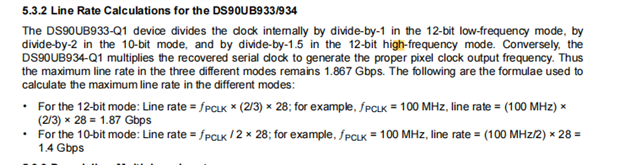
The PCLK is 96 MHz, and should be close to the calculation in the figure above, meaning that the communication becomes unstable after the transmission frequency on the coaxial cable rises from 1.4 Gbps to 1.8 Gbps.
The customer then discovered that it could be due to FB1. The customer uses the reference design recommended in 934 and the device used is the same as in the 934 manual.
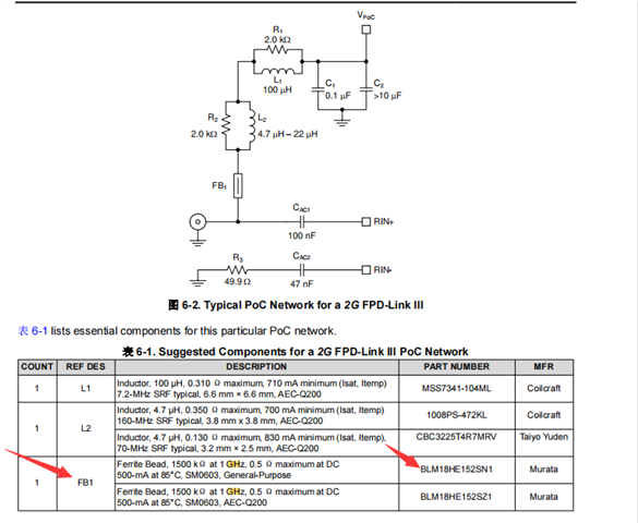
Customer try to connect a bead in FB1 in parallel, and VSYNC is much more stable than if it is not in parallel, but it still fluctuates and will fluctuate around 1 minute. According to the Bead Book for FB1, its impedance frequency curve is as follows:
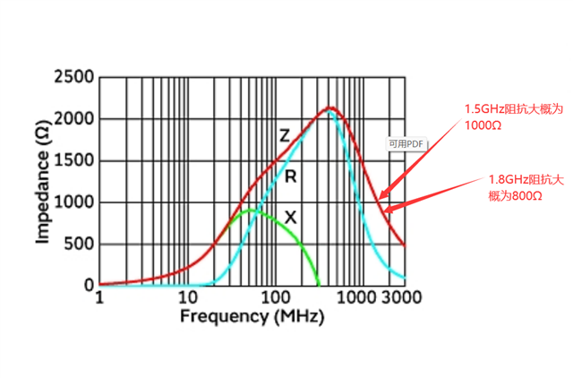
So the customer wants to confirm whether replacing the beads can stabilize the communication? For example, at 1.8 GHz, replace beads with impedance greater than 1000 Ω.
2) The worst case scenario is probably the instability of 12-bit transmissions because the cable does not support such high transfer rates. The customer does not currently have the proper instruments to test the cable for conformance.
The easiest way to do this is to replace a more suitable cable, but due to the specific application, the current cable is the most suitable one.
When only 10-bit image data is transferred reliably, does it mean that the highest 2-bit data of the image sensor is lost if 10-bit image data is selected to be transferred? Is there a remedy? For example, for 933 transfers, shift 12-bit image data right by 2, discard the lowest 2-bit data, and keep the high bits?
Could you help check this case? Thanks.
Best Regards,
Cherry
