This thread has been locked.

If you have a related question, please click the "Ask a related question" button in the top right corner. The newly created question will be automatically linked to this question.

TUSB213: USB device mode can't be recognize by Host (PC) after we added DC and AC gain to pass eye diagram test.

Part Number: TUSB213
Other Parts Discussed in Thread: TUSB217, TUSB216, TUSB216I

Hi, 

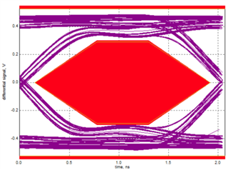
We are currently using TUSB213 in our prototype to improve our USB signal eye diagram. After applying some DC and AC gain with the signal conditioner, we are able to pass both near and far end test. However, our device can no longer connect to the USB host (PC) via a USB hub. We have tried different USB hubs and different USB cables (including different cable length) and the results are consistent. We can still connect to the PC if we connect directly to the PC's USB port. 

Strange thing is if we don't apply any DC and AC gain, even though the eye diagram looks bad but we don't have any issue connecting to the host via direction connection or USB hub. 

I have attached the USB analyzer log below. Looks like the host was having trouble identify the speed of the device when we are connecting via a USB hub. 

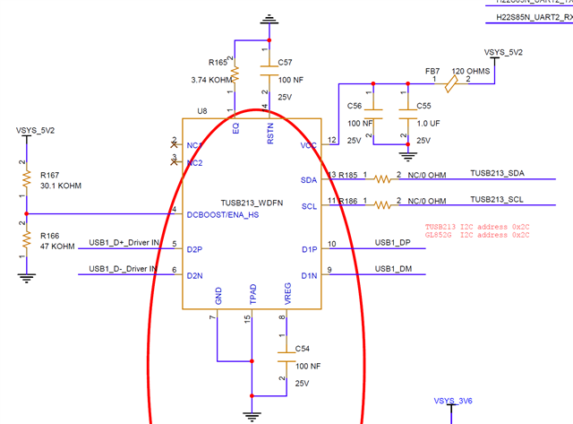
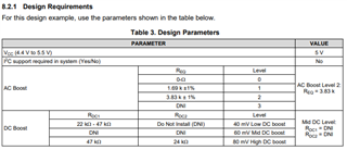
Here is a snapshot of our schematic: It is in non I2C mode, the DC gain is set to high and the AC gain is set to 2. 

Please let us know if you have any suggestion for us to try. Thank you.  

PB1 USB analyzer log (direct USB connection) - Passed.csvPB1 USB analyzer log (USB connection via USB hub) - Failed.csv

  • Hi Jefferey,

    After review of your schematic, I have some comment as below.

    • For AC Boost level 2, the resistor is 3.74k ohm, but our recommended design parameter is 3.83k ohm +/- 1%. (minimum 3.7917k ohm)
    • For high DC Boost, the pull-up resistor is 30.1k ohm, but our recommended design parameter is 24k Ohm.

    Please update the parameters and let us know if it works.

    Best,

    Josh

  • Hi Jefferey,

    One more thing, there is a high possibility that there will be too many gain.

    Best,

    Josh

  • Hi Josh, 

    We tried different gain settings but DC gain = high and AC gain = 2 is the only setting that allow us to pass the eye diagram. If we reduce the gain setting then we are not able to pass the eye diagram test. 

    BR,

    Jeff

  • Hi Jeff,

    How did you setup for the test? I also need to review the components placement. Please share the layout.

    Best,

    Josh

  • We did more testings with TUSB213 EVM and found no matter what DC and AC gain we applied, we can still get the same issue. We then tried using TUSB216 and TUSB217 EVM and it seems the issue is gone. From the datasheet, looks like TUSB216 and TUSB217 can improve signal quality without altering packet timing or adding propagation delay or latency. I think this is probably the root cause of the issue with TUSB213.

  • Hi Jeff,

    It makes sense. Because of the cable length or components placement, there might be a difference between TUSB213 and newer version redrivers. That is why I asked you layout.

    As you know, TUSB216 is designed to improve the signal quality of High-Speed USB signals under optimized settings by boosting the signal edges and also providing DC boost. Note that I would recommend using TUSB216I for your performance, it can recover more loss from PCB/cable in the signal. Also, TUSB216I has better jitter performance than TUSB213 and the package allows for both devices (at each end) to be designed.

    Best,

    Josh