This thread has been locked.

If you have a related question, please click the "Ask a related question" button in the top right corner. The newly created question will be automatically linked to this question.

USB Redriver Solution and Questions

Other Parts Discussed in Thread: TUSB212, TUSB216, TUSB216I

Hi expert,

Customer is considering to add USB redriver for application like below. 
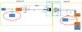
There is a main board AP and LoRa DUT.

Some questions;

1. where is recommended to place the redriver in the AP board? Close to CPU, in the middle or close to the  connector?

2. Is it also recommended to add another redriver in the LoRa DUT as well? If so, where is recommended to place it? 

3. what solution will you suggest? How about TUSB212 and TUSB216?

   - can TUSB212&TUSB216 compensate both transmission and receive channel?

4. are there any functions not exist in non-I2C mode comparing I2C mode if customer prefer not to use I2C?

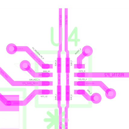
5. regarding layout, e.g. TUSB216, does it make sense that D1P short to D2P and D1M short to D2M? How does the re-redriver work if short these GPIOs directly? 
Regards,

Allan

  • Hi Allan,

    1. It would be desirable to place as close as possible to the connector.
    2. It would be desirable to place as close as possible to the connector.
    3. I would recommend using TUSB216I that is designed to improve the signal quality of High-Speed USB signals by more optimized settings.
    4. In non I2C mode (default), SDA1 would be placed with 1.8M ohm PD and CD would be placed with 500K ohm PD. Please refer to pin configurations and functions section in datasheet.
    5. Yes, D1M needs to be shorted to D2M and D1P to D2P, this is because the TUSB21X family of redrivers passively adds on to the signal it is laid over. This reference (Link) would be helpful about the concept.

    Best,

    Josh

  • Hi Josh,

    #1,2, is it recommended to add two re-drivers on both side or just one side transmit/receive is fine? 

    Regards,

    Allan

  • Hi Allan,

    The signal conditioning depends on the design, so we can't say where the placement is correct.

    It would be recommended that please place the footprint on the layout on both sides and then only populate the redriver on the AP side first. If the performance would be not expected, please place them on both sides with low settings.

    Best,

    Josh

  • Hi Josh,

    Some further questions,

    6. could you please explain more what's AC boost and DC boost and their differences? 

    7. want to double check what would be recommended RDC1/RDC2 cuz table2 suggest a value between 22kohm to 47kohm either pull-up/floating/pull-down but EVM circuit use 15Kohm pull-up/floating/pull-down?

    8. USB2.0 data D+/D- is bidirectional, if customer only put one re-driver on the AP side to compensate transmission for example, how about data direction change to be receiver? In other words, the placement of the re-driver would see different distance as transmit side point of view and receive side point of view even we place the re-driver close to the connector, but we still use the same AC&DC boost config?

    9. any concern to connect D+ to DM, and D- to DP cuz layout restriction? 

    Regards,

    Allan

  • Hi Allen,

    6. DC Boost helps to maintain the levels of VHigh and VLow in an eye diagram, which tend to accrue resistive loss in long traces and cables. AC/Edge Boost is used at edges/transition bits in a signal, and is used to ensure that signal transitions have the correct rise/fall time. This attached diagram can help to understand where exactly an AC Boost might be useful.

    7. Please follow the parameter on datasheet.

    8. As you told, it is bidirectional, so you don't need to control for data direction. They should try to place the redriver away from the CPU as much as possible in the AP layout because placing the redriver as close to the connector as possible would help minimize the amount of loss that accumulates after the redriver. I am not sure which redriver customer will use, but note that it should be set low in the initial evaluation to prevent overdriving signals and then move up from there if additional boosting is needed.

    9. USB 2.0 polarity cannot be swapped with the redriver. The D1x and D2x sides of the device can be swapped with issue assuming polarity is conserved (DP->DP and DM->DM). The redriver for USB2.0 uses DM specifically to understand if HS terminations have been enabled by USB Host and Device, if so, the redriver turns on AC and DC boost. If the device DxM pin is connected to DP this function cannot occur and boost function will not be enabled.

    Best,

    Josh

  • Josh,

    One question to #4, any reason that recommend to pull down such high resistance to GND on SDA&CD? Since I see the app note TUSB212 Schematic Checklist said we can leave them floating. 

    Regards,

    Allan

  • Hi Allan, 

    I mentioned them for internal PU/PD value for TUSB216I. If you are asking about TUSB212, you can refer to the app note. (TUSB212 schematic checklist)

    Best,

    Josh