This thread has been locked.

If you have a related question, please click the "Ask a related question" button in the top right corner. The newly created question will be automatically linked to this question.

SN65HVD251: SN65HVD251

Part Number: SN65HVD251

Hello,

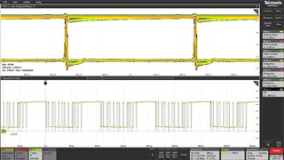
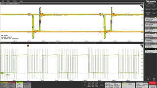
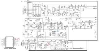
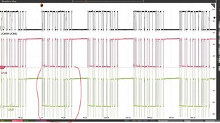
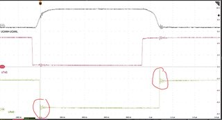
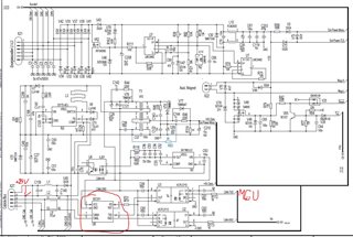
I am looking for a possible replacement for the PCA82C251T/YM,118 (NXP) circuit and we would like to use your component SN65HVD251DR. The circuit connection is in the appendix. I would need to justify why when replacing components in the circuit, there  be more interference on the edges of the signal than when using the original component (see figure below)

  .


Thanks for the anwers.
Best regards
Karel Skočík

  • The R pin of the SN65HVD251 has a higher drive strength (4 mA) than that of the PCA82C251 (1 mA).

    How long is the trace between the transceiver and the optocoupler? If it is short, then the ringing is likely to be a measurement artifact. If the trace is so long that you get transmission line effects, then it can be terminated with a source termination resistor at the R pin (like R113).

  • Thank you for answer.
    Could I have a follow-up question? I don't like the timing of the RxD signal, see Eye diagram below. What could be the reason for this? (first figure using original  PCA82C251, second figure using  SN65HVD251)

    Thanks for the anwers.
    Best regards
    Karel 

  • There is a consistent skew of about 100 ns between falling and rising edges. I'd guess that the receiver's input switching thresholds are different.

    Anyway, at 1 Mbps, it does not matter.

  • Hi Karel,

    I would recommend considering the newer TCAN1044A as a replacement here.This device will have much better availability that the older SN65HVD251 and will have better performance on the CAN bus. 

    The RXD pin for TCAN1044A is also more similar defined to your existing solution with a 2mA drive current. This may help reduce some of the overshoot you are seeing on this signal line. 

    Let me know if you have any more questions. 

    Regards, 
    Eric Schott 

  • Hi Eric,

    I have one more question about your proposed replacement. So far, I have looked at the datasheet only briefly, but it seems to me that pin 8 (see picture below) does not have exactly the same function. Can the circuit be connected to the previously sent connection (pin 8 connected via a 6k19 resistor to GND pin 2)? Replacement must be pin to pin.

    Thank you for answer.

    BR

    Karel

  • Hi Karel,

    In this schematic, the STB pin for TCAN1044A would be sufficiently biased to GND to register a low-level on the mode input. This would leave to transceiver in its Normal operating mode, which is the same behavior as with SN65HVD251. 

    The low-level leakage of the STB pin is specified to be 20µA maximum when biased to GND, which would generate a voltage of around 120mV across the 6k-ohm resistor at the pin. This is still well below the low-level input for the pin so the resistor will not be an issue for this replacement.

    Regards,
    Eric Schott