This thread has been locked.

If you have a related question, please click the "Ask a related question" button in the top right corner. The newly created question will be automatically linked to this question.

TCAN1146-Q1: Wake ON CAN

Part Number: TCAN1146-Q1
Other Parts Discussed in Thread: ESD2CAN24,

I am planning to use TCAN1146DYYRQ1 as a WAKE-UP CAN.There are few queries related 

1-Which supply rail should be active when then this CAN transceiver is configured as a WAKE UP CAN ?

2-What will be default status of the INH pin when this CAN is powered for the first time. Before any SPI communication is done.

  • Hi Sobin,

    Thanks for bringing these questions to E2E. 

    1) The TCAN1146 expects that Vsup will be present for all operational modes, including Sleep mode with partial networking active. While in Sleep mode, the Vcc and Vio supplies may be disabled to save power. The transceiver will still be able to perform the selective wake functionality. 

    2) When Vsup is first supplied, the TCAN1146 will move into Standby mode and drive the INH output high (to Vsup potential). A SPI write is required in order to put the device into any other mode.

    Let me know if you have any more questions. 

    Regards, 
    Eric Schott 

  • Thanku for the information.. As our design is progressing, i may have more queries. Will you review our schematics ?

  • Sobin,

    Yes, we can review schematics. Once they are available for review, you can either bump this thread or create a separate one.

    Regards,

    Eric Hackett

  • Eric,

    Thanks for the support.

    Does TI have any recommendation for buck convertor to be used in the WAKE-UP CAN. its expected that the nominal battery voltage is 12 but, it could vary between 6v and 30V ? Currently using LMR14020SQDPRRQ1.My application is highly sensitive ASIL-D peripherals are included.

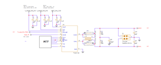
  • Hello Eric kindly review the attached schematics and share your comments

  • This schematic looks good. I don’t have any changes to recommend. See my notes below.

    • Decoupling capacitors included and valued appropriately.
    • Split capacitor included and valued appropriately.
    • Bus capacitors included and valued appropriately for a mid-sized system - ensure placement close to connector and along signal path.
    • TVS diode included - ensure placement close to connector and along signal path.
      • Please promote TI's ESD2CAN24 for CAN applications. 
    • Termination resistors included correctly and valued appropriately.
    • CMC placed nominally between transceiver and termination.
    • All pull-up / series resistances are acceptable.
      • Unused WAKE pin may be tied directly to GND for noise immunity and BOM savings. 

    Let me know if there are any questions or concerns regarding the design.

    Regards,
    Eric Schott

  • Hello Eric, 

    Thanks for the latest review.

    Is it oke to keep the 5V alive always or only after powering the MCU  ?

  • Hi Sobin,

    No issue leaving Vcc supplied while the transceiver is in Sleep mode. The only downside to this is the small amount of leakage from the supply through the IC pin will increase the Iq of the system. This will not cause any issues for the transceiver itself though. 

    Regards, 
    Eric Schott 

  • Eric,

    My question was if i am using a partial networking do i need to keep the 5v, or is it just the VSUP is enough for internal circuitry to wake the CAN to pull the INH high ?

  • Hi Sobin,

    Sorry about the confusion.

    Vsup is the only voltage rail required while TCAN114x is in Sleep mode. partial networking is possible with only this supply active. 

    Regards,
    Eric Schott

  • Eric,

    Customer is demanding to use a dual output regulator for CAN: We have almost 15 CAN Phys, Does TI have Dual output buck regulator for CAN power ?

    Also a b it confused with the power consumption calculation .Should we consider both recessive  and  dominant   for power estimation ?Here when VCC=5V and VIO is 3.3V 

    • IREC = 5mA
    • IDOM = 70mA is and consider all others to be  around 3mA is this too much  ? 

    Could you please comment on this ?

  • Sobin,

    Our team does not support power regulators, so please direct your questions about this to the correct forum.

    In terms of power consumption for CAN, both dominant and recessive consumption must be considered since CAN traffic consists of both dominant and recessive bits. Please see this thread for more detailed information.

    Regards,

    Eric Hackett 

  • Hi Eric,

    We have 21 CANs across the Board, Do we need to keep 10uF bulk decoupling caps across all the VSUP pins of these CANs ?.The Size of Caps are a Major concern.

  • Hi Sobin,

    No, each transceiver will not need its own bulk capacitor. It is sufficient to have the bulk capacitance at one point on the board to filter the Vsup line for all transceivers. 

    Regards, 
    Eric Schott 

  • Can you please provide thermal model  for Ansys Icepack ?

  • Sobin,

    We will have to submit this as a request to our thermal modeling team as this kind of model is not readily available for TCAN1146-Q1. Typically these requests take 1-2 weeks to fulfill, so I will update this thread when we have the model available.

    Regards,

    Eric Hackett