


Part Number: PCA9535
Hi team,
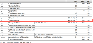
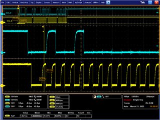
From datasheet, there is clear spec requirement of I2C input rise and fall time. If the I2C fall and rise time is out of spec, what risk will have? Thanks!
BR
Jiawei
Part Number: PCA9535
Hi team,
From datasheet, there is clear spec requirement of I2C input rise and fall time. If the I2C fall and rise time is out of spec, what risk will have? Thanks!
BR
Jiawei


