This thread has been locked.

If you have a related question, please click the "Ask a related question" button in the top right corner. The newly created question will be automatically linked to this question.

DP83TC814x-Q1 often show test failed when execute TDR test.

Other Parts Discussed in Thread: DP83TC814R-Q1, DP83TC814S-Q1

I just implement TDR follow below  and snla389,but it often show  1:1  in 0x1E[1:0]

TDR is activated by setting bit[15] in register 0x1E. The procedure is as follows.
DP83TC814S-Q1, DP83TC814R-Q1
SNLS663 – DECEMBER 2021 www.ti.com
34 Submit Document Feedback Copyright © 2021 Texas Instruments Incorporated
Product Folder Links: DP83TC814S-Q1 DP83TC814R-Q1
• Configure the DP83TC814-Q1 as per the initilization settings from SNLA389 Application Note
• Ensure that the Link Partner connected to the PHY is slient. Link will be down during TDR execution.
• Run the Pre-TDR configuration settings as listed in SNLA389.
• Start TDR by setting register 0x1E[15] to '1'.
• Wait 100ms, read register 0x1E[1:0]
– If it reads 0b10 then TDR has executed successfully.
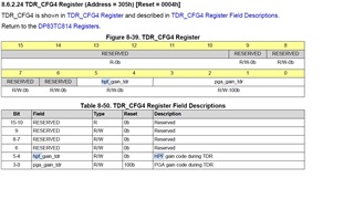
• If TDR executed successfully then read register 0x310 to get TDR results.
– 0x310[8]: 0 = Half Wire Open not detected or 1 = Half Wire Open detected
– 0x310[7]: 0 = Cable fault not detected or 1 = Cable fault detected
– 0x310[6]: 0 = Cable fault is OPEN or 1 = Cable fault is SHORT
– If valid cable fault is detected then 0x310[5:0] will store the location value in meters.

my codes like below

eth_setRegister(0x0834, 0xC001,true);
sleep(1);

eth_setRegister(0x0523, 0x0001, false);
eth_setRegister(0x0827, 0x4800, false);
eth_setRegister(0x0301, 0x1701, false);
eth_setRegister(0x0303, 0x023d, false);
eth_setRegister(0x0305, 0x0015, false);
eth_getRegister(0x0306, regVal, false);

regVal = (regVal|0x0010);

eth_setRegister(0x0306, regVal, false);
eth_setRegister(0x001f, 0x4000, false);
usleep(120000);//wait for reset
eth_setRegister(0x0523, 0x0000, false);
eth_setRegister(0x001f, 0x0000, false);

ret = eth_setRegister(0x001e, 0x8000, false); //bit15 1: Start cable measurement 0:Cable Diagnostic is disabled

while(true)
{
ret = eth_getRegister(0x001E, regVal, false);
if(ret)
{
LOG(ERROR) << std::hex << regVal << endl;
measurementResult = regVal & 0x3; //bit 0:1
if(3 == measurementResult) //complete and fail
{
val = ETHERNET_OPEN_ERROR;
// LOG(ERROR) << "cable test failed" << endl;
return ret;
}
else if(2 == measurementResult) //complete and not fail
{
// LOG(WARNING) << "cable test completed success" << endl;
break;
}
else
{
//do nothing, loop
nRetryCnt++;
if(ETH_RETRY_READ_REG_MAX < nRetryCnt)
{
val = ETHERNET_UNKNOWN;
// LOG(ERROR) << "eth_getCableDiagResult, Retry failed !!!!!" << endl;
return ret;
}
usleep(ETH_DELAY_READ_REG_MS);
}
}
else
{
val = ETHERNET_OPEN_ERROR;
// LOG(ERROR) << "cable test failed,get register failed" << endl;
return ret;
}

}

ret = eth_getRegister(0x0310, regVal, false);
if(ret)
{
// LOG(ERROR) << std::hex << regVal << endl;
if(BIT_TST(regVal,7))
{
if(BIT_TST(regVal,6))
{
val = ETHERNET_OPEN_ERROR;
// LOG(ERROR) << "eth_getCableDiagResult ETHERNET_OPEN_ERROR1" << endl;
}
else
{
val = ETHERNET_SHORT_ERROR;
// LOG(ERROR) << "eth_getCableDiagResult ETHERNET_SHORT_ERROR" << endl;
}
}
else if(BIT_TST(regVal,8))
{
val = ETHERNET_OPEN_ERROR;
// LOG(ERROR) << "eth_getCableDiagResult ETHERNET_OPEN_ERROR2" << endl;
}
else
{
val = ETHERNET_NO_FAULT;
// LOG(ERROR) << "eth_getCableDiagResult ETHERNET_NO_FAULT" << endl;
}
}

  • Hi Yang Ming,

    eth_setRegister(0x0834, 0xC001,true);

    This should be written to Register 0x1834h instead of 0x0834.

    Please refer to the TDR section in the following appnote:

    https://www.ti.com/lit/an/snla389a/snla389a.pdf?ts=1682357799346&ref_url=https%253A%252F%252Fwww.ti.com%252Fproduct%252FDP83TC814S-Q1

    Also, make sure you are following the Extended Register space access read/ write sequence mentioned in the datasheet when accessing the extended registers (Section 8.4.9):

    https://www.ti.com/lit/ds/symlink/dp83tc814s-q1.pdf?ts=1682357943409&ref_url=https%253A%252F%252Fwww.ti.com%252Fproduct%252FDP83TC814S-Q1

    Regards,
    Rahul

  • Hi,I have tried 0x0834->0x1834,but it the same ,other status link link status/master,slave/SQI/phyid...etc I got ok,just TDR failed.

    and I fount if I don't configurate "Reg[0x0305] = 0x0015",it will be ok, 

    So , I have questions below:

    1:Is it necessary configurate 305 during TDR?

    2:if it is , what the problem? How could I solve it?

    3:about register 1834 and 0834,I see access 0834 in driver example(link:Gitweb @ Texas Instruments - Open Source Git Repositories - git.TI.com/gitweb - ti-analog-linux-kernel/analog-linux.git/blob - drivers/net/phy/dp83tc812.c),not access 1834 like Datasheet . why?

    driver codes:

    if (dp83812->is_master)
    ret = phy_write_mmd(phydev, DP83812_DEVADDR_MMD1, 0x0834, 0xc001);
    // ret = phy_write_mmd(phydev, DP83812_DEVADDR, 0x0834, 0xc001);
    else
    ret = phy_write_mmd(phydev, DP83812_DEVADDR_MMD1, 0x0834, 0x8001);
    // ret = phy_write_mmd(phydev, DP83812_DEVADDR, 0x0834, 0x8001);

    datesheet

    8.6.2.89 MMD1_PMA_CTRL_2 Register (Address = 1834h) [Reset = 8000h]

  • I also found if I useing the head like below connect the wire, will also cause TRD failed.(1Eh bit 0 tdr_fail is 1), whether 2 pins TRD_P/TRD_M is open,short,connect.

  • Hi Yang,

    Without configuring Reg[0x0305] = 0x0015, TDR is passing ?

    Regards,
    Rahul

  • Hi Yang,

    In the driver DP83812_DEVADDR_MMD1 is offsetting the value 1.

    1:Is it necessary configurate 305 during TDR?

    Yes, it has to be used as mentioned in the appnote.

    We have tested TDR with Automotive connectors on the ends but not with banana grabbers. 

    Can you try testing it with a automotive connector ?

    Thanks,
    Rahul

  • I have using automotive connectors instead, but it seems the same ..the register 0x305 must configure to 0x15? or need according to  actual situation?

    and what these 2 fileds(hpf_gain_tdr,pgd_gain_tdr) used for in TDR?

  • Register 0x305 must be configured as mentioned in the app note.

    Can you please share the register writes being written ? and also pictures of your test setup?

    Thanks,
    Rahul

  • Hi Rahul

    below is the initial codes in my driver:

    static void indirect_write(struct phy_device *phydev,u32 regnum, u16 val)
    {
    phy_write(phydev, 0x0d,0x1f);
    phy_write(phydev, 0x0e,regnum);
    phy_write(phydev, 0x0d,0x401f);
    phy_write(phydev, 0x0e,val);
    }

    static void indirect_write_mmd1(struct phy_device *phydev,u32 regnum, u16 val)
    {
    phy_write(phydev, 0x0d,0x01);
    phy_write(phydev, 0x0e,regnum);
    phy_write(phydev, 0x0d,0x4001);
    phy_write(phydev, 0x0e,val);
    }

    static int ti81x_soft_reset(struct phy_device *phydev,bool isHardReset)
    {
    u16 mdio_data = 0;

    mdio_data = phy_read(phydev,0x1f); //reg : PHYCR

    if(isHardReset)
    {
    BIT_SET(mdio_data,15);
    }else
    {
    BIT_SET(mdio_data,14);
    }

    phy_write(phydev,0x1f,mdio_data);

    msleep(100);

    printk("ti81x_soft_reset %d**\n",isHardReset);

    return 0;
    }

    init codes:

    indirect_write(phydev,0x523,0x0001);//disable link-up start until configuration is complete

    mdio_data = indirect_read_mmd1(phydev,0x0834);//access MMD1,


    BIT_SET(mdio_data,14);
    BIT_SET(mdio_data,0);
    indirect_write_mmd1(phydev,0x0834,mdio_data);//configure PHY Master

    indirect_write(phydev,0x81c,0x0fe2);
    indirect_write(phydev,0x872, 0x0300);
    indirect_write(phydev,0x879, 0x0f00);
    indirect_write(phydev,0x806, 0x2952);
    indirect_write(phydev,0x807, 0x3361);
    indirect_write(phydev,0x808, 0x3d7b);
    indirect_write(phydev,0x83e, 0x045f);
    indirect_write(phydev,0x834, 0x8000);
    indirect_write(phydev,0x862, 0x00e8);
    indirect_write(phydev,0x896, 0x32cb);
    indirect_write(phydev,0x03e, 0x0009);
    //indirect_write(phydev,0x01f, 0x4000);
    //indirect_write(phydev,0x523, 0x0000);

    ti81x_soft_reset(phydev,false);

    msleep(100);

    phy_write(phydev, 0x01, 0x0065);

    indirect_write(phydev,0x523, 0x0000);//Enable link-up start after end of configuration

  • below is register function in upper APP level, called by the first codes.

    static bool eth_setRegister(const uint32_t registerNumber,const uint32_t registerValue,const bool isMMD1 = false)
    {
    uint32_t dEvad1 = 0x001f;
    uint32_t dEvad2 = 0x401f;

    if(false == eth_creatSocket())
    {
    return false;
    }

    if(isMMD1)
    {
    dEvad1 = 0x0001;
    dEvad2 = 0x4001;
    }

    strncpy(ifr.ifr_name, "eth0", IFNAMSIZ);
    if (ioctl(skfd, SIOCGMIIPHY, &ifr) < 0)
    {
    cout << "read ethernet address failed" << endl;
    close(skfd);
    skfd = -1;
    return false;
    }

    //usleep(10000);
    mii_val = (struct mii_ioctl_data *)(&ifr.ifr_data);
    mii_val->reg_num = 0x0D;
    mii_val->val_in = dEvad1;
    if(ioctl(skfd, SIOCSMIIREG, &ifr) < 0)
    {
    cout << "set 0xD register first failed" << endl;
    close(skfd);
    skfd = -1;
    return false;
    }

    //(10000);
    mii_val->reg_num = 0x0E;
    mii_val->val_in = registerNumber;
    if(ioctl(skfd, SIOCSMIIREG, &ifr) < 0)
    {
    cout << "set 0xE register failed" << endl;
    close(skfd);
    skfd = -1;
    return false;
    }

    //usleep(10000);
    //mii_val = (struct mii_ioctl_data *)(&ifr.ifr_data);
    mii_val->reg_num = 0x0D;
    mii_val->val_in = dEvad2;
    if(ioctl(skfd, SIOCSMIIREG, &ifr) < 0)
    {
    cout << "set 0xD register first failed" << endl;
    close(skfd);
    skfd = -1;
    return false;
    }

    //usleep(10000);
    //mii_val = (struct mii_ioctl_data *)(&ifr.ifr_data);
    mii_val->reg_num = 0x0E;
    mii_val->val_in = registerValue;
    if(ioctl(skfd, SIOCSMIIREG, &ifr) < 0)
    {
    cout << "set 0xD register first failed" << endl;
    close(skfd);
    skfd = -1;
    return false;
    }

    close(skfd);
    skfd = -1;

    return true;
    }

  • this is the connector we using now .replace the banana connector.

    Test step:

    1:When the NAD module which with the 814 phy work up, we call a NAD api,  then will install PHY ko driver which work to initial through the initial codes I mentioned up . then we will see the eth0 in upper app  level through ifconfig command.

    2: :Let wire open,or short by tweezers or connect other terminal.

    3:Then we start a eth test example.which mentioned up (the first codes in my first part).then this example will start the TDR.

  • Hi Yang Ming,

    Thank you for sharing the details, let me review the register sequence and update you.

    Regards,
    Rahul

  • Hi Rahul,any update???

  • Hi Yang Ming,

    Apologies for the delay in response, I got swamped with queries.

    The code share above is to initialize the PHY and for PHY functionality. Looking at the above statements, my understanding is that DP83TC814 is able to link up and you can verify it using ifconfig ?

    Are you forcing the speed to 100 ? as DP83TC814 supports only 100M and does not support ANEG.

    phydev->speed = SPEED_100;
    2: :Let wire open,or short by tweezers or connect other terminal.

    As you mentioned the wire should be left open in order to run TDR (no Link Partner should be connected).

    Are you running this on a Linux system ? 

    I have tested the TDR method on an EVM and was able to measure the values. Do you have an EVM to test this method ?
    https://www.ti.com/tool/DP83TC812EVM-MC

    Regards,
    Rahul

  • 1:I have forcing the speed to 100.

    2:I running this on a Linux system.But I don't have EVM.

  • Hi Yang Ming,

    Can we perform an individual register read/ write sequence using phytool or mdio tool ?

    The register sequence mentioned in the app note works and we can test it on an EVM. I am trying to think of ideas of how we can debug in your case.

    Regards,
    Rahul