This thread has been locked.

If you have a related question, please click the "Ask a related question" button in the top right corner. The newly created question will be automatically linked to this question.

DP83867IR: Always getting link status as 1 without connecting the ethernet cable

Part Number: DP83867IR

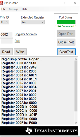
we are developing a board using DP83867 as the ethernet phy, we need help with its configuration as when I read the link status register, I always get 1 even without connecting the ethernet cable. So, is there any specific way of configuring it??

  • Hi Benz,

    Which link status register bit are you referring to? Do you think you could provide a schematic of your board?

    Best regards,

    Melissa

  • I am referring to the Basic Mode Status Register (BMSR), Address 0x0001 bit 2 which is the link status. Sorry I won't be able to provide you with the schematics. I just want to know the step by step configuration from the beginning.

  • Hi Benz,

    Bit 0x0001[2] should be 0 by default when the PHY is powered up and no cable is attached. I have tested this on our EVM to confirm. 

    If it is defaulting to 1 during power-up, there may be a design issue.

    Best regards,

    Melissa

  • No, I can assure you that there are no design issues, as our board works fine with linux. Now we are developing it for windows 10 IOT operating system. But I am not asking help in developing windows 10 IOT OS, I want to know what can cause the link status to be always 1. Does the link status come from the interrupt pin ??

  • Hi Benz,

    The link status register tells you if link is up MDI side. It does not come from the interrupt pin.

    Can you provide a register dump from 0x0000-0x001E?

    I've also attached a DP83867 Troubleshooting Guide for your reference, please take a look at it: https://www.ti.com/lit/an/snla246b/snla246b.pdf

    Best regards,

    Melissa

  • The PHY Interrupt pin INT/PWDN is connected to SAI1_RXD1 of iMX8MP SOC. We have done the muxing of IOMUXC_SW_MUX_CTL_PAD_SAI1_RXD1 as ALT5_GPIO4_IO[3] — Select mux mode: ALT5 mux port: GPIO4_IO03 of instance: gpio4.

    As part of interrupt config of MDIO, this gpio GPIO4_IO03 is configured as EDGE FALLING. This config was performed in device tree as part of our linux BSP.

    Below are the information passed to Windows driver from ACPI table,

    a)MAC address

    b)Cortex A53 Interrupt for  Ethernet 1

    c) MDIO Bus Controller Input Clock as 266000 KHz

    d) Phy Address

    e) Phy Interafce Type as "0"  for RGMII

    f) Phy Max MDIO Bus Clock 15000 KHz

    g) Phy Minimum STA HoldTime 10 ns

    h) Preamble is enabled

    The driver gets this ACPI information and use for the configuration in OS side.

    You can get the IMX8MP reference manual by clicking the link https://www.nxp.com/webapp/Download?colCode=IMX8MPRM  for your reference.

    Can you tell me what can cause the link status to be always 1?? 

    Please confirm if such configuration is required in general for any OS platform with respect to PHY and SoC.

  • Is there any other way to know if the ethernet cable has been connected to the ethernet port or not??

  • No Bit 0x0001[2] is 0 by default during power up. But after that it is always 1 with or without connecting the ethernet cable.

  • Hi Benz,

    Please provide a register dump from 0x0000-0x001E so we may help you debug this issue.

    Best regards,

    Melissa

  • Sorry I am not able to take the register dump in windows, can you tell me if there is any way to take register dump??But I can tell you the individual bit values of any registers. Also can you tell me how can I find that the interrupt pin has been enabled or not through software?? 

  • Hi Benz,

    Sorry I am not able to take the register dump in windows, can you tell me if there is any way to take register dump??But I can tell you the individual bit values of any registers.

    If you are able to provide me the values of registers of 0x0000 - 0x001E that is fine.   

    Also can you tell me how can I find that the interrupt pin has been enabled or not through software?? 

    You can read/write to 0x001E[7] to enable the pin as an interrupt output. 

    Best regards,

    Melissa

  • Can you please tell me what are the things that could cause link status to be always 1, so that I can sort them out?? I am not able to provide you with the register dump because the driver is different in windows. 

  • Hi Benz,

    You mentioned you would be able to provide the individual bit values of any registers. I just need the values of registers 0x0000-0x001E so I can try to help you figure out what is causing your link status issue. 

    Best regards,

    Melissa

  • Hi 

    I have got the register dump 

    ============================================
     === Dump PHY registers ===
     ============================================
     phy[0x00] = 0xFFFF
     phy[0x01] = 0xFFFF
     phy[0x02] = 0xFFFF
     phy[0x03] = 0xFFFF
     phy[0x04] = 0xFFFF
     phy[0x05] = 0xFFFF
     phy[0x06] = 0xFFFF
     phy[0x07] = 0xFFFF
     phy[0x08] = 0xFFFF
     phy[0x09] = 0xFFFF
     phy[0x0A] = 0xFFFF
     phy[0x0B] = 0xFFFF
     phy[0x0C] = 0xFFFF
     phy[0x0D] = 0xFFFF
     phy[0x0E] = 0xFFFF
    phy[0x0F] = 0xFFFF

  • Hi Benz,

    It looks like you are not correctly accessing the PHY's registers through MDC/MDIO, the values should not all be 0xFFFF. This issue can be caused by reading the incorrect PHY address. How did you configure your PHY address on the board and what address are you reading from?

    Best regards,

    Melissa

  • I think according to IEEE 802.3 standards these register addresses are common for most of the ethernet phys. So I think we are not reading the wrong address. Can you tell me if there is any specific pin initialisation that needs to be done for any pins or mdio pin?? Is there any specific clock setting for DP83867?? Because the code which we are using was modified for RTL8211F ethernet phy, but it should work for DP83867, but I think we are doing something wrong regarding the phy specific initialisation part of DP83867. By default DP83867 is in power down mode right, so will that might be the issue ??

  • We have two ethernet phys and they have separate MDIO buses. For the first phy we have not strapped any RX_D pins but we have strapped RX_CTL pin to mode 3, for phy 2 we have strapped the RX_D0 pin to mode 2 and RX_CTL pin to mode 3, other RX_D pins are not strapped, so the phy address for the first phy will be 0 and for the second phy it will be 1 right??

  • Hi Benz,

    A correct register dump will look something like this.

    If you want to confirm your PHY address settings, check  section 8.5.4 PHY Address Configuration. It is difficult for me to assess your straps without seeing the schematic. 

    It is also possible that the invalid register readings are caused by power-up sequence issues. Are all the requirements in section 7.6 Power-Up Timing being followed?

    Best regards,

    Melissa

  • Hi Melissa,

    Can you tell me how to power on the phy, because I think it is by default in power down mode right?? Will it just power up automatically if the board turns on ??

  • Hi Melissa,

    Is there a way to find out if the phy has been powered on correctly?? Also is there a way to set the interrupt/power down pin as interrupt pin without using the registers?? The phy address is correct. The driver we use in windows is not phy specific, rather it is a generic driver, but the changes related to the ethernet phy is done only in the acpi table and board init file where the pin muxing and clock settings are done.

  • Hi Benz,

    The PHY is not powered at all by default, the power lines have to supplied even in power down mode. 

    If your board follows all of our design requirements, and the power of the board is connected to the PHY's power, the PHY should power on automatically when the board turns on. You may use our schematic checklist to check your board design.

    4442.DP83867_Schematic_Design_Review_Checklist (1).xlsx

    Are you trying to access the registers through your driver or MDIO/MDC?

    Best regards,

    Melissa

  • Hi Melissa

    Thank you so much for answering my questions

    I asked about the power because the pin INTERRUPT / POWER DOWN is by default in power down mode as mentioned in the datasheet.

    Our ethernet phy is directly connected to the MAC, so I guess we are accessing the register through mdio. But how can we access the registers through drivers without mdio/mdc??

  • Hi Melissa

    I went through the schematic checklist that you shared and found that the reset pin was not grounded in our board, but even after that it still works in ubuntu so is it necessary to ground the reset pin and connect a capacitor to it ???

  • Hi Benz,

    Our ethernet phy is directly connected to the MAC, so I guess we are accessing the register through mdio. But how can we access the registers through drivers without mdio/mdc??

    So are the MDIO/MDC lines connector to the MAC processor aswell? You need MDIO/MDC to access the registers.

    I went through the schematic checklist that you shared and found that the reset pin was not grounded in our board, but even after that it still works in ubuntu so is it necessary to ground the reset pin and connect a capacitor to it ???

    How is your Reset pin connected? The schematic diagram shows the Reset pin typically connected HIGH, but it can be pulled LOW with the button in the schematic.

    Best regards,

    Melissa

  • Yes, the MDIO/MDC pins from the phy is connected to the processor. The reset pin is pulled up and is connected to the SOC. In windows we use NDIS miniport driver for ethernet.

  • Hi Benz,

    The reset pin configuration is ok. Let's circle back to investigating the PHY address and PHY power configuration to figure out why you are reading 0xFFFF. 

    We have two ethernet phys and they have separate MDIO buses. For the first phy we have not strapped any RX_D pins but we have strapped RX_CTL pin to mode 3, for phy 2 we have strapped the RX_D0 pin to mode 2 and RX_CTL pin to mode 3, other RX_D pins are not strapped, so the phy address for the first phy will be 0 and for the second phy it will be 1 right??

    Could you provide a screenshot of just this part? If you do not want to share it publicly, you may DM me.

    For the power - are you in 2 supply or 3 supply mode? When operating in three-supply mode, the 1.8-V VDDA1P8 supply must be stable within 25 ms of the 2.5-V VDDA2P5 supply ramping up. There is no sequencing requirement for other supplies when operating in three supply mode.

    Best regards,

    Melissa

  • Hi Melissa

    I have asked for permission to send the schematics, so once I get the permission I will DM you. Regarding the phy, is there a way to find out whether the RX_CLK is being generated or not??

  • Hi Benz,

    You can probe it directly with a scope.

    Best regards,

    Melissa

  • Hi Melissa

    I have dm you the screenshots of our schematics.

    Do you have any porting guide to port from RTL8211F to DP83867??

  • Hi Benz,

    Unfortunately we do not have such a guide.

    Best regards,

    Melissa

  • Hi Melissa

    Does DP83867 have any drivers in windows or is there any specific settings for DP83867 in windows in general?? Does DP83867 support NDIS miniport driver in windows?? Is there any support from TI regarding windows drivers in general??

  • Hi Benz,

    For our industrial PHYs, we have Linux drivers that are available publicly here: https://git.kernel.org/pub/scm/linux/kernel/git/torvalds/linux.git/tree/drivers/net/phy 

    Best regards,

    Melissa