This thread has been locked.

If you have a related question, please click the "Ask a related question" button in the top right corner. The newly created question will be automatically linked to this question.

SN65HVD1786: RS485 Communication testing with 4000ft cable and 20 nodes in simulation

Part Number: SN65HVD1786

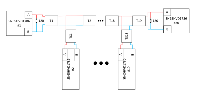
We are working on testing RS485 communication on 4000ft cable with simulation. There are 2 ways to test RS485 communication.

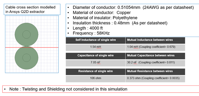
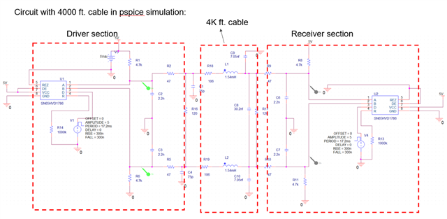
1. Consider RLC parameter for 4000ft cable and do the simulation with 4000ft cable and 20 nodes.

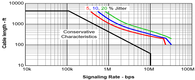
2. Consider RLC less than 1/20th times Wavelength of the operating frequency, as per transmission line theory.

Which method do we need to take from above 2 methods. It is ok to use directly 4000ft cable for testing RS485?? 

  • Hi Swarupa,

    So either of the options that you have listed are possible - with option 2 being the more "accurate" system model - but for the most accurate cable modeling in a system simulation for RS-485 please see the below diagram - this is assuming that an ideal topology is used - which for RS-485 is daisy chaining or a spine with junction boxes - and each terminal node is terminated (that being the first and last node on bus are terminated with 120 Ohm resistors as in standard)

    The red line denotes the "A" wire and the blue line denotes the "B" wire.

    There are 2 more components in the simulation:

    Tx - which represents a lossy transmission line - most spice programs are going to have a transmission line model built into them (I believe the symbol is 'O') - what you need to provide is electrical parameters and length of section of cable - so the RLC + length of cable section. Where length is going to be the length of Tx or the length of the bus between stub branches.

    TSx - represents lossy transmission lines that are the stub length - these should max out at a length <= Tr/10 * Vp where Tr is the differential transition time and Vp is the signal propagation velocity in the transmission medium. This max length should reduce these stubs effects as these nodes should be unterminated as only 2 terminations are allowed in a standard RS-485 system.  If you daisy chain TSx will approach 0mm (it won't be 0 - but it essentially is for most purposes) 

    Now there is a rather large caveat to all of this - the Spice model of this device is an extremely idealized model - its using an older model architecture that is more idealized than our current one - and our current architecture is still idealized - so this model is missing most of the nuance of the device - and the nuance matters a lot when looking at signal integrity versus bus length for these parts - so while the above instructions will give a good approximation of the system - the actual models for the nodes are very idealized so it may not show everything relevant to the design. So testing in a lab setting if possible is always preferred with large cables in the system as simulations tend to be too simplistic compared to a real system. 

    Also I will say - that 4000 feet is going to technically be over the 1.2km max of RS-485 ( about 20 meters/65 feet longer than standard max- so it might not be as a big of an issue - but something to be aware of) and the speed really is going to be limited to be about 100kbps if everything is ideally setup in the system - since this part is a bit faster on its transitions as well it could further hinder this part at those large bus lengths. If there needs to be a faster speed applied or longer distance  - we do have a repeater design that might also be of use - https://www.ti.com/lit/ug/tidu590/tidu590.pdf?ts=1683045174886


    Please let me know if you have any other questions!

    Best,

    Parker Dodson 

  • Thanks, Parker, for the help.

    As you said both options are ok to use for that i have two questions.

    1. If we go with option 1 directly using 4000ft RLC value in that case Is Jitter/Signal integrity can cause any issue to signal as because data rate is approx 100Kbps for 4000ft.

    Do u have practical results of testing with 4000ft cable with you?? if yes can you please share with us.

    2. If we go with option 2, for this how much length do i need to consider and repeat it till 4000ft??

  • Hi Swarupa,

    1. There could be jitter/SI issues if you simulate the first way as its an assumption that we can remove the transmission line effects. Its much easier of a simulation to perform - and since the IC model is very idealized a more advanced solution still won't capture all of the nuance of the source / loads. 

    2.  So we have a generalized cable guideline that we use - I am not sure what part it was directly taken with (it really shouldn't matter - as this is supposed to be a stand-in for any RS-485 device)  - but it was taken with a 22 AWG cable, 120Ω, unshielded twisted pair - as you can see the conservative characteristics will be slightly below 4000ft. as mentioned below because it just out of range for standard RS-485 

    That being said - we don't have specific data on this part to share because its usually not taken with devices and 4000ft > 1.2km. That being said the cable, the layout, and bus topology are going to impact the system greatly - so with large busses its almost always necessary to physically test in your operating environment. 

    3. If you were to use the second option - you would limit each RLC to be equivalent to 1/10th of a wavelength of the highest significant harmonic that you care about - so at 100kbps you will you fundamental at 50KHz, 3rd at 150KHz, 5th at 250KHz, 7th at 350KHz, and 9th at 450KHz - so I'd use either the 7th or 9th harmonic to get as close to reality as possible. You can use 1/20th of the length - but that may be a little overkill as generally 1/10 is usually fine and if you really need to get more accuracy 1/16 is usually the lowest I will see - but mainly 1/10. You can go lower - but it probably isn't necessary.

    4. As stated in my first reply - both simulation options are possible - but spice has built in lossy transmission lines - and I'd highly suggest using that functionality if you are going to go with spice - or use a high frequency analysis tool to analyze the cable and idealized loads if simulation is still wanted. Nothing is going to be more accurate than real world testing and transmission line design is very complex - so I do worry that regardless of which direction you go simulation wise that a lot of real world nuance is going to be missed - but if you have to simulate in spice option 2 or lossy transmission lines are the best way to go.

    Best,

    Parker Dodson

  • Hi Parker,

    As you suggested both options are ok. We have gone with option 1 i.e., directly we did 4000ft simulation of cable in ANSYS tool.

    Would you please check and let me know your thoughts / any suggestions.

    Thanks.

    below are Specification and results of simulation of cable in ANSYS tool.

    Also, we did simulation in PSPICE using values we got from cable simulation in ANSYS tool.

    Results of Pspice simulation.

  • Hi Swarupa,

    I think how you have set up your simulation is fine and I think its about as accurate as you can be with the IC model that we have using the simplest transmission line model as you have in your simulation. 

    That being said it doesn't capture all of the nuance of the system - for that type of simulation option 2 that you mentioned or the alternative option that I mentioned is going to be more accurate as the transmission line will be more accurate since this is ultimately a lumped model and not a distributed one. However with the IC model that we have - and how your circuit is setup I think its an okay approximation and I think it shows a possibility of working - however the nuance in long-bus applications like this could be the difference between failure and a successful operating system.

    Please let me know if you have any other questions.  

    Best,

    Parker Dodson