This thread has been locked.

If you have a related question, please click the "Ask a related question" button in the top right corner. The newly created question will be automatically linked to this question.

TUSB216: TUSB216 doesn't seem to work when running device compliance test

Part Number: TUSB216
Other Parts Discussed in Thread: , TUSB213EVM, TUSB217A, TUSB213, TUSB217

Hi, 

We tried running compliance test with TUSB216 (in device mode) but the eye diagram looks exactly the same no matter what the gain settings were. I read that TUSB216 might have some interpretability issues during compliance testing and TUSB216i has some updates to address this specific issue. 

1. Can you confirm if TUSB216 has interpretability issues for compliance test?

2. How do we confirm if it is same issue that we are having?

Regards,

Jeff

  • Hi Jeff,

    We didn't have any issue that you are having for TUSB216. Just put the previous thread for tracking. (Link)

    • If you followed the test fixture procedure, now we can approach the device internally. Since the eye diagram shows no change, it means the device is not working properly. Please see this app note. (TUSB2xx High-Speed Signal Quality Test Modes - SLLA593) Did you have that the test fixture is connected to TUSB216 before enabling the source to send the TEST_PACKET? How did you set up for the test? Note that it should be started with the redriver configured at the lowest settings to prevent overdriving the signals.
    • Could you confirm if you checked the TUSB216 reference schematic in the datasheet for the parameter placement?
    • I might need to review the schematic and layout. Please share them if you want me to do so.

    Best,

    Josh

  • Hi Josh,

    There is a TUSB21XX Test Mode Compatibility table in TUSB2xx High-Speed Signal Quality Test Modes - SLLA593.

    Looks like TUSB216 doesn't support device test mode. Do you think this could be why the eye diagrams were unchanged during our compliance test (device mode)? 

    Currently we are just testing it with the TUSB216 EVM so we don't have any schematic to share at the moment. 

    We also tested our system with TUSB213EVM and TUSB217AEVM the same way and we were able to get the eye diagram to change when we adjust the gain settings. 

    Regards,

    Jeff 

  • Hi Jeff,

    I missed you are testing in Device mode. As you shared the Test Mode Compatibility table, TUSB216 doesn't support the Device mode.

    In Host mode, a system sends test packets downstream, where they are received and measured. In Device mode, a host system sends a test packet command to a connected device downstream. Upon receiving this command, the device sends test packets upstream, where they can be measured and analyzed.

    If you want the Device mode, TUSB216I or TUSB217A would be considered. Based on the previous thread and this thread, I would recommend using TUSB216I for your performance. 

    Best,

    Josh

  • Hi Josh,

    What are the major differences between TUSB216I and TUSB217A? I can't see any obvious difference in terms of function and performance from the datasheet (other than TUSB216i has wider temperature range). However, we received a quote for both and the cost of TUSB216I is significantly higher than TUSB216 and TUSB217A. 

    Regards,

    Jeff

  • Hi Lam,

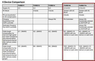
    The most difference between TUSB216I and TUSB217A is the battery charging control mode. Please below tables for the comparison. 

    To clarify the background, could you please provide the desired function or information such as mode, battery charge control mode, etc.. Also, could you confirm that you were trying to change the redriver from TUSB213 to pass the test?

    Best,

    Josh

  • Hi Josh,

    For desired function, our system needs the redriver to work in both host and device mode. We don't need battery charge control function. 

    Yes, we confirmed that TUSB213 can provide enough gain for our eye diagram to pass. However, when we were testing on the application level, the latency from TUSB213 is causing some compatibility issues for us (PC can't detect USB device when the connection is made via a USB hub). 

    Best, 

    Jeff

  • Hi Lam,

    TUSB217A is only the compatible with TUSB213 with host and device mode.

    As I mentioned on the previous thread, TUSB213 has too many gain as your setting is DC gain = high and AC gain = 2. Just wanted to check if the test with DC gain = middle and AC gain = 2 was not also able to pass. Could you share if you have DP and DN data on scope? 

    Best,

    Josh

  • Hi Josh, 

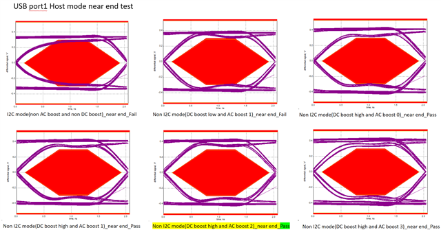
    Here is the eye diagram test with TUSB213 under different gain settings

    Note that I was having compatibility issue (previously mentioned) in almost all gain settings. However, we didn't have any issue when tested with TUSB217. 

    Best,

    Jeff

  • Hi Lam,

    Thank you for sharing the eye diagram. I was wondering if you also tested at Mid DC Boost. The compatibility issue would be happened because of too much gain even if the eye diagram test is passed. That is why I asked about the DP & DN data.

    Note that about DC boost and AC boost as you might know. DC Boost helps to maintain the levels of VHigh and VLow in an eye diagram, which tend to accrue resistive loss in long traces and cables. AC Boost is used at edges/transition bits in a signal, and is used to ensure that signal transitions have the correct rise/fall time.

    TUSB217 is only compatible with Host mode, so TUSB217A would be alternative for Host and Device mode both.

    Best,

    Josh

  •  I2C mode,when both SDA and SCL are pulled up, TUSB216I will enter I2C mode, then we perform the following steps, The Tusb216I will work according to the I2C setting, right?

    1、set CFG_ACTIVE bit to high (get into configuration mode)
    2、change gain settings
    3、set CFG_ACTIVE bit to low (get back to normal mode)
    4、Trigger RESET

    Non-I2C mode when both SDA and SCL are not pulled up, Tusb216I will work in Non-I2C mode according to the settings of BOOST and RX_SEN.

    Is this understanding correct? Looking forward to your answer, thank you.

  • Hi Oliver,

    You are right. Note that In I2C Mode, SDA and SCL pins should be placed with pull-up resistors(depending on I2C bus voltage). If both SDA and SCL are pulled up at power-up the device enters into I2C mode. In non-I2C mode, pull-down and pull-up resistors for RX_SEN pin must follow RRXSEN1 and RRXSEN2 resistor recommendations.

    Best,

    Josh

  • Hi Josh, 

    For I2C mode, do we need to toggle the reset after we change the gain and sensitivity settings?

    We would like to know what is the correct process. Just steps 1-3 or 1-4

    1. Set CFG_ACTIVE bit to high (get into configuration mode)
    2. Change gain settings
    3. Set CFG_ACTIVE bit to low (get back to normal mode)
    4. Trigger RESET

     Thanks,

    Jeff

  • Hi Jeff,

    Thank you for the clarification. You don't need to reset after I2C changes. Please follow 1-3 steps.

    When it gets reset, the I2C registers will be reset to their default value. More info can be found in section 7.4.6 of the datasheet or in the timing requirements section of the datasheet. In section 7.4.6 on datasheet, "It is advised to set CFG_ACTIVE bit before changing values. This halts the FSM, and reset it after all changes are made." it means clear it after all changes are made.

    Best,

    Josh

  • Hi Josh, 

    Got it. Make sense to me now. 

    Thanks,

    Jeff

  • Hi Jeff,

    No problem. Please let me know if you have any further questions. I close this thread.

    Best,

    Josh