This thread has been locked.

If you have a related question, please click the "Ask a related question" button in the top right corner. The newly created question will be automatically linked to this question.

TLIN1024A-Q1: 2CH vs. 4CH Schematic

Part Number: TLIN1024A-Q1
Other Parts Discussed in Thread: TLIN1024-Q1

Hi,

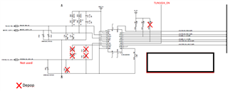
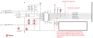
My customer has a TLIN1024A-Q1 question. In 'high content' vehicles they use all the channels but on the 'low content' vehicles they only use two. What changes would need to occur for the different versions? Are the changes on the schematic shared in the post the right changes?

Thanks,

Tom

  • Tom,

    If channels 3 and 4 are not being used, then VSUP2 can be left unpowered. In this situation, the third and fourth channels would be off, while the other two channels could still be used.

    I'm not sure I fully understand the comment in the red text in the corner of the image (perhaps there is context I am missing). The EN signals will become irrelevant if VSUP2 is disconnected. However, if VSUP1 = VSUP2, then yes, you'd need to control EN3 and EN4 separately from EN1 and EN2.

    I recommend disconnecting VSUP2 if possible, because note that the device powers up into Standby mode if EN = low. This means that if you simply tie EN3 = EN4 = OFF, then the channel would power up into Standby mode. You'd need to toggle EN3/EN4 to transition the device to Sleep mode for maximum current consumption savings.

    You wouldn't need the passives anymore if VSUP2 is removed. You could DNP them.

    Also, it looks like the TLIN1024-Q1 is on their schematic; please check to make sure they are using TLIN1024A-Q1.

    Best,

    Danny

  • Hi Danny,

    Thank you for the response. Would it make sense for them to add 0Ohm resistors on the EN lines to depopulate those as well?

    When talking with the engineer they mentioned that the VSUP2 line might have to stay connected. If that's the case can you provide feedback on the depop questions in the schematic below? What you the system concerns be? What state would the device be in? Would an EN signal on EN3 cause any concerns?

    Thanks,

    Tom

  • Hi Danny,

    Additional Question: Based on my understanding, the LIN3 channel would be open on the connector side and the TRX/RXD will be internally terminated on the MPU side. (with the changes to the schematic above). Is that correct?

    Thanks,

    Tom

  • Tom,

    Would it make sense for them to add 0Ohm resistors on the EN lines to depopulate those as well?

    Functionally it will not cause reliability concerns to do so. Disconnecting EN will allow the internal pull-down to disable the channel, but note that the channel will be in Standby mode rather than Sleep mode, so the tradeoff is marginal current consumption increase.

    See the yellow line in Figure 9-4.

    Additional Question: Based on my understanding, the LIN3 channel would be open on the connector side and the TRX/RXD will be internally terminated on the MPU side. (with the changes to the schematic above). Is that correct?

    Yes, and floating LIN pin is okay. There is an internal termination on the bus side that will hold the line high, and the biasing to the MCU-side pins will also keep them in a known state.

    Best,

    Danny