This thread has been locked.

If you have a related question, please click the "Ask a related question" button in the top right corner. The newly created question will be automatically linked to this question.

DS90UB953-Q1: Part of the signal is lost when using UB953 I2C to communicate with the device

Part Number: DS90UB953-Q1

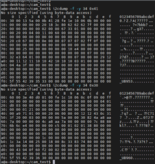
Hello, we are using UB962 (system) with 4 UB953 (cameras) in an asynchronous state, and we have found that the I2C signal output by UB953 is inconsistent with the signal output by the system to UB962 in specific camera modules. This issue occurs because there is a lot of data to be output through I2C, and the signal loss starts to happen in the middle or later stage of the output process. Please refer to the image below. There are no other devices on the UB953 I2C bus that could affect the signal. This problem occurs on some cameras but not on others. Interestingly, the abnormal cameras do not exhibit any abnormality in the I2C signal when they are set to synchronous mode. Could you advise us on which areas we should check?

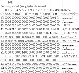
This is the signal in normal state.

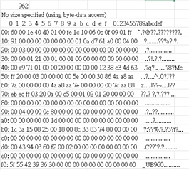
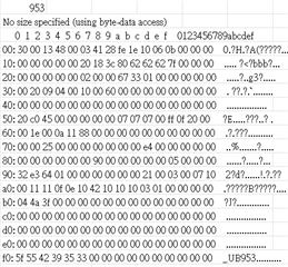
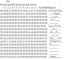
This is the signal in abnormal state.

  • Hi Chung,

    • Can you send a 953 register dump and 962 register dump when you see the abnormal I2C condition? 
    • Can you try probing the LOCK GPIO of the abnormal cameras and see if it stays high the entire time? If LOCK drops, that could cause I2C communication issues between the DES and SER.
    • Did you design the camera modules? It would be good to check whether the external clock connected to the 953 CLKIN pin is meeting the input clock jitter specification in the datasheet

    Regards,

    Cindy

  • Hi Candy

    • Can you send a 953 register dump and 962 register dump when you see the abnormal I2C condition? 

    0x41 is the dump of register 953, and 0x30 is the dump of register 962.

    Other issues require the assistance of my colleagues for confirmation, and I will reply later. Additionally, I have replaced the farkra cable and 962 module, and found that the abnormal 953 can occasionally work properly (953 and 962 are in asynchronous state), which makes me doubt whether the Back Channel can really reach 10Mbps. I would like to ask if there is a way to confirm the connection quality and standards of 953 and 962 in the asynchronous state?

    Thank you

  • Hi Chung,

    I noticed in the 953 register dump that there are many CSI errors in the received CSI packets (0x5C and 0x5D) along with back channel errors (0x52 and 0x55-0x56). 962 is also reporting bidirectional control channel errors and CSI errors at the RX Port.

    Can you try using the FPD-Link MAP tool (see user guide here) to evaluate link quality? Typically issues on the bidirectional control channel are due to the channel link quality or unstable lock. You can run the MAP tool with the old fakra cable/module and new fakra cable/module to see the difference. If this issue you are seeing is only on some cameras and swapping the cable and/or module is helping, it may be a system hardware issue. 

    Another debugging step would be running patgen from 953 to 962 to see if you still get issues with the imager off. 

    Regards,

    Cindy

  • Hi Candy

    I'm sorry for the late reply. I have used the FPD-Link MAP tool and obtained two results. I would like to verify their accuracy.

    1.962:non-sync     953:sync

    2.962:non-sync     953:The original 953 hardware was in sync mode, and the software switched it to non-sync mode

    I don't understand why there is a difference between these two results, and whether it will affect occasional failures in the I2C. How can this be improved?

    I hope you can help me answer.

    Thank you.

  • Hi Chung,

    I see that in both of the register dumps, 953 is in non-sync internal clock mode based on register 0x03. Is this what the 953 is strapped to, or are you overriding the mode? If you are operating in non-sync mode, the 960 back channel must be 10Mbps, not 50Mbps which is what it is showing in the first test result. That is why the margin is narrow and there is no lock. In the result with the better margin, 960 register 0x58 is at the correct back channel value (10Mbps) to be paired with 953 in non-sync mode.

    Regards,

    Cindy

  • Hi Candy

    I apologize for not explaining clearly. Initially, the 953 was in synchronous mode, and the 962 was in asynchronous mode (50Mbps), as shown in the first result. In this state, there is a low probability of I2C failures when using I2C to configure the 953 or ISP. The second result shows that the original synchronous mode of the 953 (953:reg0x03=0x5b)was overridden to become asynchronous, and the reverse channel of the 962 was set to 10Mbps(962:reg0x58=0x5a). In this state, there is a high probability of I2C failures when using I2C to configure the 953 or ISP. Comparing the two results, the second result may seem better, but I cannot understand why I2C fails occur. Could it be due to incorrect SerDes settings, poor SerDes signal quality, or other reasons?

    Thank you.

  • Hello Chung,

    Cindy is Out of office and will be back in 3 days.

  • Hi Chung,

    Thank you for the clarification, I realize I was looking at the wrong register value in the dump. Also note that 50Mbps backchannel corresponds to the term synchronous mode for both 953 and 960.

    The first result shows that the link margin is failing (see this MAP tool user guide for the passing criteria). Poor link quality can be due to the cable, connector, layout, etc.

    For the second result, the higher number of I2C errors is likely due to a high number of back channel CRC errors reported in 953 register 0x52 and 0x55-0x56. The MAP tool only reports forward channel errors, so that is why the margin may look good even if you are getting I2C errors. For back channel link quality, you can continuously monitor the CRC error count in 953 registers 0x55-0x56. Back channel CRC errors again indicate poor link quality due to the cable, connector, layout, POC filter, etc. I recommend checking these factors.

    Regards,

    Cindy