This thread has been locked.

If you have a related question, please click the "Ask a related question" button in the top right corner. The newly created question will be automatically linked to this question.

TCA9509: TCA9509

Part Number: TCA9509
Other Parts Discussed in Thread: EK-TM4C1294XL, TCA9555,

Hello,

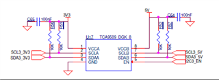
We are trying to interface an LED display board driven by TCA9555 which is I2C based to TM4c1294 Launchpad ( EK-TM4C1294XL).  We are able to interface the TCA9555 directly and able to drive LEDs which are working.  However it works for only for 15 minutes and after that the TCA9555 is out of control and does not respond at all.   Since we are using a cable of 20 cm  we tried to put a repeater in between based on TCA9509.  However once the A side of TCA9509 is connected to controller, there is no pulses on clock (SCL) and data(SDA) and hence no communication,  We removed the inputs side pull up of TCA9509 and checked

Regards,

Ramesh

DocScanner Apr 12, 2023 5-37 PM.pdf

In TC9509 En pin is actually pulle up.'

  • Hi Ramesh,

    So it looks like you can communicate  with the TCA9555 for a short time, meaning that TM4C is correctly sending I2C data and receiving ACKs from the TCA9555. The clock is correctly clocking in data and the TCA9555 is accepting data changing output states effectively. 

    I have a couple probing questions about the system. Is there a point in the system application where the TCA9555 is sourcing current from all of the LEDs connected to it? I noticed in the attached pdf that all p-ports are being used. Are you sure that the total current through ICC is not being violated, and there is no way you could have over current the device? 

    Can you power-on-reset the TCA9555 and re-drive LEDs for another 15 minutes after the first lock up? 

    Do you know the temperature conditions of the device? Is the device overheating from sourcing much current from all of the attached LED's? 

    Do you see this error occur across multiple TCA9555?

    If this issue is a current/power consumption issue, I would suspect an I2C buffer such as the TCA9509 not to be much help since buffers are solutions to highly loaded busses. They help to re-drive I2C signals when there is more than >400pF of parasitic capacitance present on the bus.

    However once the A side of TCA9509 is connected to controller, there is no pulses on clock (SCL) and data(SDA) and hence no communication,  We removed the inputs side pull up of TCA9509 and checked

    Is this connection made before or after the 15 minutes have passed?

    Regards,

    Tyler

  • Hi Tyler,

    Thanks for the clarifications.  Actually now we are able to communicate for more than 2 hours also without any issues after putting some ferrite beads reduce the noise.    I feel there is no current issue since it works for more than 2 hours.   

    So I understood  that I2c buffers is not required for cable length of 20 cm.  Can you confirm. 

    How to do the Power on reset- Should we disconnect the Power wire and re connect?

    There is no temperature issue

    The issue occurs across multiple TCA9555 also. 

    But I am not able to understand why the clock and data are stopped when tCA9509 is connected in between.  Can you throw some light on this?.

    Regards,

    Ramesh

  • Hi Ramesh,

    Thanks for the clarifications.  Actually now we are able to communicate for more than 2 hours also without any issues after putting some ferrite beads reduce the noise.    I feel there is no current issue since it works for more than 2 hours.   

    This is interesting that failures take so long to occur. I would be interested in the scope captures of the I2C bus before and after the ferrite bead is added to see the differences in the waveform. It might be possible that the ESR of the ferrite bead is helping filter out some high-frequency noise on the I2C bus. 

    What do you mean by the statement...

    TCA9555 is out of control and does not respond at all

    Are you able to see the device NACK? Or does it occur that when you send the correct slave address, the TCA9555 does not send anything back? Have you tried to oscillate the clock signal to attempt to free the SDA bus? Are there other I2C devices on the bus that could be in contention?

    So I understood  that I2c buffers is not required for cable length of 20 cm.  Can you confirm. 

    The answer to this question is situational. I2C standards have a specific amount of parasitic bus capacitance that can be present on the bus at any given time. The standard for 100kHz, 400kHz is 400pF. Depending on the type of cable, each cable will introduce some capacitance per length. You would have to look at the spec of your specific cable. On a pcb, you can estimate trace capacitance to be ~3pF / inch of trace. 

    As long as your I2C bus is not heavily loaded with parasitic bus capacitance, you do not need a re-driver / buffer. Only in cases where the bus nears the 400pF limit would you need to add an I2C buffer. 

    How to do the Power on reset- Should we disconnect the Power wire and re connect?

    When power (from 0V) is applied to Vcc, an internal power-on reset circuit holds the TCA9555 in a reset condition until Vcc has reached Vpor. At that time, the reset condition is released, and the TCA9555 registers and I2C-SMbus state machine initialize to their default states. After that, Vcc must be lowered to below Vporf and back up to the operating voltage for a power-reset cycle. 

    But I am not able to understand why the clock and data are stopped when tCA9509 is connected in between.  Can you throw some light on this?.

    I just noticed in the schematic image you provided that you have 10k pull-up resistors on the A-side of the 9509. These need to be removed since the 9509 integrates a 1mA current source on the A-side. There is no need to include pull-up resistors on the A-side. These pull-ups might be interfering with the VILC spec, which is the low-level voltage contention spec, and may not be able to pass signals from the A-side to the B-side. 

    Remove the pull-up resistors on the A-side, and see if communication resumes with the buffer in place. 

    Regards,

    Tyler

  • Hi Tyler,

    Sorry I am on travel and could not reply.  For the below point

    "But I am not able to understand why the clock and data are stopped when tCA9509 is connected in between.  Can you throw some light on this?."

    I have put a 10 microfarad decoupling capacitor( instead of 2.2microfarad) to TCA9555 and now it is working fine in bench.  However We are designing a powersupply which has lot of noise inside the unit.  Because of that this stop working after sometime.

    Regards,

    Ramesh

  • Hi Ramesh,

    Sorry for the late reply, I was out of office. 

    "But I am not able to understand why the clock and data are stopped when tCA9509 is connected in between.  Can you throw some light on this?."

    It looks like the TCA9509 in your circuit has 10kohm pull-up resistors on the A-side of the device. I am sure that there are also other devices connected to the A-side of the I2C bus as well. 

    TCA9509 has a spec called low-level voltage contention or VILC for the A-side. VILC must be met at all times for the A-side in order for a LOW to be passed from A-side to B-side. The 10kohm pull-up resistors R56 and R51 need to be removed since TCA9509 implements a 1mA current source connected up to VCCA. The addition of pull-up resistors and extra sources of current may make it difficult for every device on the A-side to be able to pull the I2C bus below a VILC. If the controlling device cannot pull its output low voltage VOL below a VILC, then you can expect TCA9509 to function incorrectly. 

    I would remove those resistors R56 and R51, and any other sources of pull-up current on the A-side that could affect the VOL levels and re-check to see if TCA9509 can pass signals. 

    I have put a 10 microfarad decoupling capacitor( instead of 2.2microfarad) to TCA9555 and now it is working fine in bench.  However We are designing a powersupply which has lot of noise inside the unit.  Because of that this stop working after sometime.

    This sounds like the supply is noisy and is causing data issues to the TCA9555 over time. A strong decoupling capacitor would filter out supply noise which could effect the signal lines which makes sense why a stronger decoupling cap would fix the issue. My recommendation if you can't place such a high decoupling capacitor in the final design is to add small series resistance on the I2C lines/p-ports in order to help filter high-frequency signals, or slow down the data rate.

    Regards,

    Tyler

  • I am still on travel this week.  Actually we have tried removing the A side pull up and then TCA9555 stopped responding!   After I come back I will try putting the series resistor in I2c lines.

    Regards,

    Ramesh

  • Hi Ramesh,

    Are there any other devices connected to the A-side of the bus?

    This is telling me that the TCA9555 is on the A-side. Is it possible to flip the buffer? Connect the TCA9509 B-side with pull-up resistors to the TCA9555 while removing pull-up resistors from the A-side? 

    Regards,

    Tyler