This thread has been locked.

If you have a related question, please click the "Ask a related question" button in the top right corner. The newly created question will be automatically linked to this question.

TCAN4550-Q1: Questions about crystal

Part Number: TCAN4550-Q1

Hi,

Goal: Communicate in CAN2.0b on CAN FD bus with microcontroller without CAN FD interface. And maybe later to communicate in CAN FD on CAN FD bus with same transceiver. 

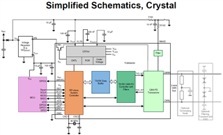
As explained in datasheet, we need a crystal of 20MHz to communicate up to 2Mbps and 40MHzs for 5Mbps.

As we would like only communicate in CAN2.0b and filter the CAN FD frame, is the quartz from MCU must be at 20 or 40MHz ?

This question because, our microcontroller can't accept a quartz above 16MHz. Is it possible to do something with our actual crystal at 8MHz?


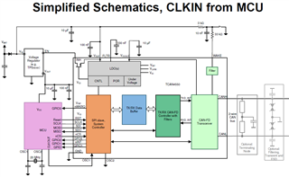
 The second solution, is to have a crystal directly on TCAN4550-Q1.

As we need to keep the 8MHz on MCU, could we have some problem with two quartz on PCB?

Thank's for your help,

Regards,

Bastien Flückiger

  • Hi Bastien,

    The TCAN4550-Q1 requires it's own crystal of either 20MHz or 40MHz, or it needs to be provided a single-ended clock of the same frequency (20MHz or 40MHz) because these frequencies are required to generate the CAN communication.  If a single-ended clock is used, it should swing between 0V and VIO (either 3.3V or 5V).

    The MCU can use a slower clock frequency such as 8MHz or 16MHz which are common frequencies and this frequency only impacts the SPI frequency with regards to the TCAN4550-Q1.  The maximum supported SPI frequency is 18MHz, but any frequency less than 18MHz can be used.  I would note that all communication with the TCAN4550-Q1 including all transmitted and received message data for the CAN bus, is sent through SPI, so a slow SPI frequency can limit the overall CAN message rate that can be achieved.

    Unless you use some sort of clock synthesizer or PLL device that can create all the different clock frequencies needed by the MCU and TCAN4550-Q1, you will likely need 2 crystals on the PCB.

    Regards,

    Jonathan

  • Hi Jonathan,

    Thank you for your answer. I have enough information now.

  • Hi Jonathan,

    One more question. If we use a 20MHz quartz to manage communication up to 2Mbps and we are on a bus where there are 5Mbps communications. Could we be perturbed or the CAN transceiver will not take into acount the communication above 2Mbps ?

    Regards,

    Bastien

  • Hi Bastien,

    Yes, you will generally need a faster crystal frequency to support 5Mbps.  This comes down into how CAN and CANFD generate the bit timing and use the clock cycle of the crystal to create a unit of time called a "time quantum" or "tq".  Then each bit period is created with a minimum of 4 tq per bit and preferably more.  The CAN bit rate is created by telling the CAN controller how many tq there are in each bit and therefore the bit rate must be an integer multiple of the clock frequency.  This is why 20MHz and 40MHz crystals are typically used because they create integer multiples of the common data rates.

    In addition to configuring the number of tq per bit, you must also set the sample point location in the bit period by allocating how many tq are before the sample point, and how many tq are after the sample point. This is usually expressed as a % where the start of the bit period is 0% and the end of the bit period is 100%.  A sample point of 80% is generally recommended because this allows time for the signal to stabilize following a dominant to recessive transition that can cause some ringing on the bus and lead to bit errors if sampled too quickly.

    With a 20MHz crystal, 5Mbps is technically possible because this will create 4tq (20MHz / 5Mbps = 4tq).  However, this is the absolute bare minimum needed per bit and will likely be prone for more bit errors because there is no tolerance for error.

    With a 40MHz crystal, 5Mbps has 8tq per bit (40MHz / 5Mbps = 8tq).  This allows increased clock tolerance margin and better adjustment of the sample point withing the bit period that will lead to more reliable operation and fewer bit errors.

    if you try to run 5Mbps with a 20MHz crystal, you will likely see an increased error count that could ultimately lead to a bus off condition where the transceiver removes itself from participating in bus communication completely.

    Regards,

    Jonathan

  • Hi Jonathan,

    Thank's a lot for your informations.

    Regards,

    Bastien

  • Hi Bastien,

    You're welcome.  I'll close this thread, but feel free to reach back out if you have any more questions.

    Regards,

    Jonathan

  • Hi Jonathan,
    We go further with this design and we have another question.

    Could we have some problem if we have also a sensor on the SPI at an other frequency (Sensor at 44kHz and CAN transceiver at 2MHz) ?

    Or can we have both at 2MHz but without problem to ensure the CAN communication at 2Mbps or 5Mbps?

    Thank's for your help,

    Regards,

    Bastien

  • Hi Bastien,

    The SPI frequency is completely independent of the CAN communication frequency.  The only requirement is that the SPI frequency be about 2MHz lower than the Crystal/Clock frequency supplied to the OSC1/2 pins.  Because the TCAN4550-Q1 recommends a minimum clock frequency of 20MHz for CAN communication, the max SPI frequency has been set to 18MHz. But any SPI frequency less than 18MHz would work including 44kHz.

    However, just note that a slow SPI frequency will take longer for the MCU to read and write the TCAN4550-Q1's registers and Message RAM space.  This will increase the time needed to send and receive a single CAN message and reduce efficiency or total message throughput.

    Regards,

    Jonathan

  • Hi Jonathan,

    Thank you for these clarifications.

    Regards,

    Bastien

  • Hi Bastien,

    I am happy to help. 

    Regards,

    Jonathan