This thread has been locked.

If you have a related question, please click the "Ask a related question" button in the top right corner. The newly created question will be automatically linked to this question.

TCAN4550-Q1: TCAN4550 Oscillator

Part Number: TCAN4550-Q1
Other Parts Discussed in Thread: TCAN4550

Hi,

I have a question about the oscillator setup for the TCAN4550. I used the suggested crystal (NX2016SA-40M) which is shown in the application example in the datasheet, with parallel 8.2pF capacitors at the crystal pins.

Is this a valid design where the TCAN works properly within it's whole temperature range (-40°C - 125°C)??
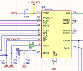
regards

Tobias

  • Hi Tobias,

    The schematic looks good and the NX201SA-40M crystal has been used extensively with the TCAN4550.  The parasitic capacitance of the PCB trace also factors into the overall Capacitive Load (Cload) and Resistive Load (Rload) which determine how the voltage amplitude and frequency of the oscillation waveform.  This parasitic capacitance can vary from board to board and therefore some testing and optimization may be needed to ensure proper operation across the full temperature range of -40C to 125C.

    Because the TCAN4550 supports both a crystal and a single-ended clock configuration, there is a detection circuit that monitors the OSC2 pin for a "grounded" pin by looking for a low voltage less than 100mV.  The key factor to stability is to ensure the capacitors and series dampening resistor creates an waveform with an appropriate amplitude to prevent the voltage from creating a false detection of a "grounded" pin which could cause the device to switch modes.

    The recommendation is to determine the appropriate capacitance needed for your PCB design and then adjust the value of the series dampening resistor to limit the current flowing through the crystal and reduce the drive level (or power dissipation) in the crystal and reduce the peak-to-peak amplitude of the oscillation to ensure the OSC2 voltage is above the detection threshold.  Typical values of a series resistor (if needed) should be less than 100 ohms.

    The parasitic capacitance will vary with temperature because the dielectric material in the PCB is not temperature stable like in high quality ceramic capacitors.  Therefore, as temperature changes, the Cload and Rload will slightly change which will also cause a slight change to the oscillation waveform.  Therefore you will need to verify your circuit across the temperature range you need to support.

    More detailed information can be found on the TCAN455x Clock Optimization and Design Guidelines application note.

    Regards,

    Jonathan