This thread has been locked.

If you have a related question, please click the "Ask a related question" button in the top right corner. The newly created question will be automatically linked to this question.

DP83869EVM: Setting registers via external MDIO pins

Part Number: DP83869EVM
Other Parts Discussed in Thread: DP83869, USB-2-MDIO

Hello,

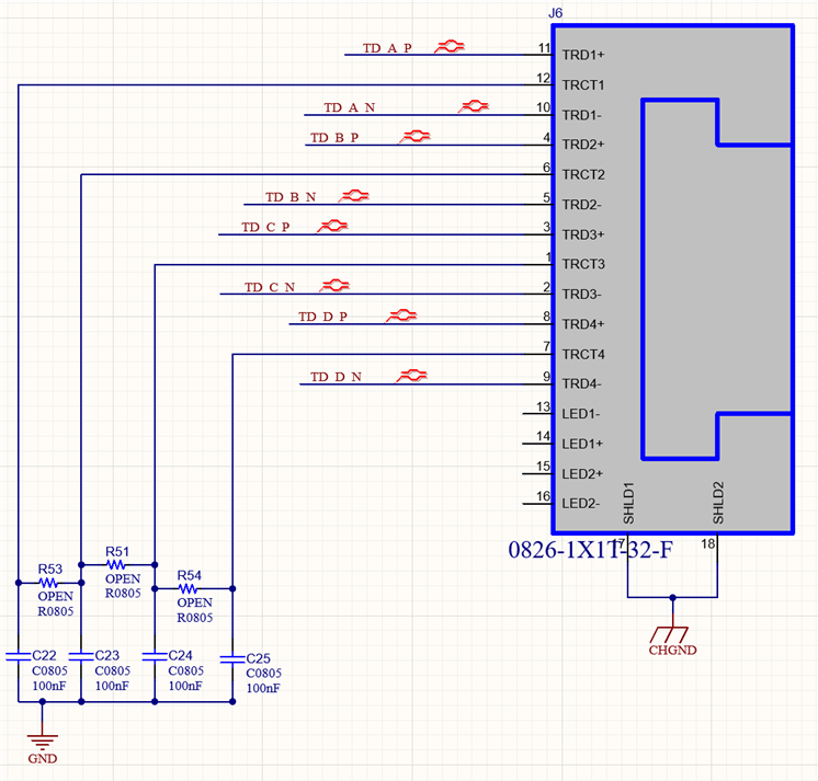
I am having some trouble figuring out how to set registers in the DP83869 by using a launchpad via the external MDIO pins on the eval board.

I had no issues setting registers via the on-board MSP430 using the USB-2-MDIO software. I was able to see a single COM port and a single PHY through that port. I was able to write and read back to confirm successful writes. 

Using the launchpad, I was able to flash the MCU (the red and green lights are both lit now). When using the USB-2-MDIO software, the launchpad shows two COM ports. There is the "debug interface" which does not show any PHY addresses. This makes sense to me. There is also the 'application UART' which shows all PHY addresses as available. When trying to set registers, I get a mix of timeout errors and errors which say "Error! Improper length format in extended register read/write." Some write commands go through, but they don't read back as set. I have tried a number of different PHY addresses under the 'application UART' port.

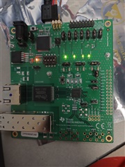
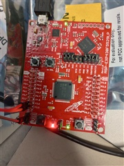
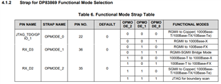
There was some inconsistency in the USB-2-MDIO guide between pictures and instructions about which jumpers should be open/closed on the launchpad. Wondering if I have some of these set incorrectly. I have attached the configuration for both boards.

Thank you.

  • Hi Ryan,

    If there are no issues with the onboard MSP430, why do you want to attach an external MSP430 board to access the registers?

    Best regards,

    Melissa

  • Because I will need to use the launchpad to set registers in the future for other chips. I have been messing around with it today and I was able to get the launchpad talking with the DP83869 on the eval board. I have a prototype DP83869 circuit which is still giving me issues, however. I am only able to read and write to the registers when the PWDN mode is enabled. I noticed that on my prototype I don't have an external pull-down from JTAG_CLK to GND. Would this somehow prevent me from accessing registers via MDIO? I am running in 1000 media converter mode. As far as I can tell, I have the chip configured correctly.

    I have set the OPMODE pins [0] = OPEN, [1] = OPEN, [2] = 2.5k Pull-up

    I have also set the LED pins [0] = 0, [1] = 1, [2] = 1

     I am curious what changes between normal and PWDN mode which might prevent me from accessing the registers. Can you think of anything that may cause this?

  • Hi Ryan,

    Let me try to set this up and get back to you. 

    Best regards,

    Melissa

  • Hi Ryan,

    I was able to access the registers using an external MSP430 without any issues.

    Here are the steps to get it working:

    1. Power and flash the external MSP430 with nothing attached to it. Then, unplug the MSP430.

    2. On the EVM: Switch the jumper on J34 to connect PCB to 5V-LDO instead of 5V-USB. This will ensure that the built-in MSP430 is not powered. 

    3. Power the EVM externally using the 'Supply' pins with a 5V-20V source.

    4. Connect the P4.2, P4.1, and GND of the external MSP to MDIO, MDC, and GND on the EVM. 

    5. Power up the MSP and access the registers.

    Note that the error "Error! Improper length format in extended register read/write," just means that the value register being read/written must be 4 decimals in length. So if you want to read register 0x0, you must input '0000', or if you want to write '140' to register 0x0, you must input '0140'.

    Best regards,

    Melissa

  • As I mentioned, I was able to get it working with the EVM board and my current issue is with a PCB that I have copied the circuit to. I did remove a few things which I thought I did not need, including the pull-down on pin 21. I can only write to the registers normally when the chip is in power down mode (using a pull-down on pin 44). I have the pull-downs set as I mentioned in my previous post. Is there something about this pull-down or possibly another pin which would cause me to be unable to access the registers unless I was in PWDN mode?

  • I removed the pin 21 pull-down from an EVL board and it did not affect my ability to access the registers, so it doesn't seem like that's the problem. I am going to try replacing the DP83869 today to see if I damaged it. Initially, the 1.1V pins were being supplied with a voltage outside of spec (around 1.5V), so it's possible the chip was damaged before this power issue was fixed. I will update with whether or not that worked.

  • Hi Ryan,

    Ok. Let me know if the new chip works.

    Best regards,

    Melissa

  • It seems like my situation has improved some after changing the chip out. I can now read and write registers outside of PWDN mode. Unfortunately, I still have some issues. The registers get reset when I cycle power, not allowing the mode to be remembered (mode 4). Using the eval boards, I can cycle power, unplug, etc. and the registers retain their settings. I am also unable to get my board to run properly in media converter mode. I have probably re-checked my straps and all other connections 10 times at this point and I cannot find anything wrong, even though there must be. Any guess at what might cause the registers to be reset when I shut down power or when I power up? 

  • Update to this - It seems that I had a bad solder joint on one of my strap resistors. This was forcing me to RGMII to Copper on start-up (000 instead of 100).

    I still do not have communication working but I am going to go back and re-check that everything is good with all of the communications connections.

  • Hi Ryan,

    Thanks for the update. Please let me know if you are able to get communication working. As for your question: 

    Any guess at what might cause the registers to be reset when I shut down power or when I power up? 

    The registers will always reset to default values when you power cycle the PHY, do a hard reset, or do a software reset.

    If you would like to preserve the register values, you may do a software restart by setting bit 14 of register CTRL (1Fh) to 1.

    Best regards,

    Melissa

  •  Hi,

    I have not yet been able to establish communication. The auto-negotiation is succeeding on the EVM but not on my custom board. From register 1, I am reading 7969 from EVM and 7949 from custom board. Here are the register contents for all of the registers described in the datasheet with all registers which contain differences highlighted. Reviewing the datasheet, it looks like they are mostly result of auto-negotiation failing. The EVM seems to be able to see the partner device on my custom board but the custom board doesn't see the EVM. Also notice sync established in register 004F on custom board but not on EVM. Anything jump out at you? I'm not really sure how to fix the auto-negotiation issue.

    Register Address EVM Register Contents Custom Register Contents
    0 1140 1140
    1 7969 7949
    2 2000 2000
    3 A0F3 A0F3
    4 1 1
    5 CDE1 0000
    6 006F 0064
    7 2001 2001
    8 5006 0000
    9 300 300
    A 7800 0000
    D 401F 401F
    E 0 0
    F F000 F000
    10 5048 5048
    11 BB02 0002
    12 0 0
    13 1942 0040
    14 29C7 29C7
    15 0 0
    16 0 0
    17 40 40
    18 6150 6150
    19 4004 4004
    1A 2 2
    1E 12 12
    1F 0 0
    25 480 480
    2C 141F 141F
    2D 2000 0000
    2E 221 221
    31 10B1 10B1
    32 50 50
    33 0 0
    37 0 0
    39 0 0
    3A 0 0
    43 07A0 07A0
    4F 0200 0196
    55 0 0
    6E 180C 180C
    86 77 77
    134 1000 1000
    135 0 0
    170 0C0E 0C0F
    180 752 752
    181 C850 C850
    182 5326 5326
    183 A01E A01E
    184 E976 E976
    185 19CF 19CF
    190 0 0
    191 0 0
    192 0 0
    193 0 0
    194 0 0
    195 0 0
    196 0 0
    197 0 0
    198 0 0
    199 0 0
    1A4 0 0
    1A5 0 0
    1A6 0 0
    1DF 44 44
    1E0 417A 417A
    1EC 1FFC 1FFC
    C00 1140 1140
    C01 6149 6149
    C02 2000 2000
    C03 A0F3 A0F3
    C04 20 20
    C05 0 0
    C06 4 4
    C07 2001 2001
    C08 0 0
    C10 3148 3148
    C18 01FF 01FF
    C19 0020 0000
  • Hi Ryan,

    So you're connecting the EVM to your custom board and it's showing link on the EVM side but not the custom board side? Do you think you could capture the specific changes you made to the EVM schematic to your custom board? Are your jumper wire settings the same?

    Best regards,

    Melissa

  • Sure. Here are the relevant pieces from the custom board. The jumper settings are the same, as noted by register 006E of each DP83869.

    document1.pdf

  • Hi Ryan,

    It looks like you are not establishing link on either side, please try the following:

    1. Restart auto-negotiation when the boards are connected together and reread the registers afterwards

    2. If you have multiple custom boards, try connecting them together to see what happens then.

    It looks like you did not change anything on the magnetics side or the straps, is this correct? Did you change the stack up at all? 

    Best regards,

    Melissa

  • I have tried restarting auto-negotiation multiple times without success. I am not establishing a link but auto-negotiation was successful on the EVM in this case. I have tried precisely the same ethernet jack and transformer which were used on the EVM, I have also tried a magjack which has everything integrated. The straps seem to be the same, as shown in register 006E.

    As far as the stack-up, the custom board is a 4-layer instead of 6-layer on the EVM. My dielectric layers, etc. are thicker and I am using 1 oz copper on the outer layers because it is a prototype board. My traces are quite short both to the SFP and to the ethernet side, about 1" each. I do have a continuous ground plane under the traces. My thought would be that this should be fine since the custom board was able to successfully advertise its specs to the EVM. Perhaps there could be an issue with the receiving side. I will test the board by attempting to overwrite the straps and do a software reset. I will see if I can get a connection in 100Mbps mode. If it's a stack-up issue, my guess is that it should work at this slower speed. I will get a script working using two EVMs and then try with the custom board.

  • I used straps to configure the EVMs in 100Mb media converter mode and was successful. Still unsuccessful at getting communication with custom board. From what I've read, it looks like the auto-negotiation pulses happen at 10Mbps, so it seems unlikely that a stackup difference would cause issues with this part.

  • Hi Ryan,

    Thanks for the detailed update. So the EVMs don't even work at 1000 Mbps? If this is the case, part of the issue may be the cable you are using. 

    With the stack up, is it possible that you introduced new stubs by moving around signal lines between different layers or have some power plane on top of  a signal line?

    Best regards,

    Melissa

  • Not 1000 or 100, and I guess not even 10 if that is in fact the speed of the auto-negotiation pulses. Maybe the cable but it works fine between 2 EVMs. 

    My copper pairs are single-layer only, on the top layer. No power planes under on any layer, there are only a couple of places where a 2.5VDC trace crosses perpendicularly on layer 3. Layer 2 is a continuous ground plane under all of the differential pairs as well as the DP83869.

  • Following up again on this.

    Can you please clarify what should be done with pin 23? The EVM has a pull-up on this but seems to run in two-supply mode since there is no 1.8V on the board. The datasheet says that pin 23 should be pulled down for 2-supply mode and pulled up for 3-supply mode. 

  • Also curious about the LED indicators. When I connect my board to an EVM via fiber and apply power to both boards, The EVM has the Link and 1000BT Link LEDs light up solid and the Activity LED blinks. On my prototype test board, only the 1000BT Link LED lights up. After several seconds, all of these lights go out on both boards, presumably after they give up on establishing a link between each other. Any insight on those status LEDs?

  • Hi Ryan,

    Apologies for the delay, I was on vacation/Holiday over the last few days. 

    Also curious about the LED indicators. When I connect my board to an EVM via fiber and apply power to both boards, The EVM has the Link and 1000BT Link LEDs light up solid and the Activity LED blinks. On my prototype test board, only the 1000BT Link LED lights up. After several seconds, all of these lights go out on both boards, presumably after they give up on establishing a link between each other. Any insight on those status LEDs?

    So two TI EVMs connected together work at all speeds, 1000 Mbps included?

    What is on layer 3? Is it the same as the TI EVM? 

    Also curious about the LED indicators. When I connect my board to an EVM via fiber and apply power to both boards, The EVM has the Link and 1000BT Link LEDs light up solid and the Activity LED blinks. On my prototype test board, only the 1000BT Link LED lights up. After several seconds, all of these lights go out on both boards, presumably after they give up on establishing a link between each other. Any insight on those status LEDs?

    Thank you for pointing it out, that is a typo in the datasheet. DP83869 will automatically know rather it is in two supply mode or three supply mode. There is no strapping configuration required to set the PHY into two supply mode and three supply mode. The DP83869 doesn't need any pull up resistors on pin 23 for three supply mode. We will edit the datasheet.

    ...

    Assuming your operation mode is 0, no RX or TX activity is being detected. It is interesting but unfortunately it does not point me to a specific direction as to what your issue is. I will check with the team to see if they have any thoughts.

    Here's a document you may find helpful for debugging, it is for the DP83867, but the same ideas apply to the DP83869:

    https://www.ti.com/lit/an/snla246b/snla246b.pdf 

    Best regards,

    Melissa

  • There is nothing on my 3rd and 4th layers under the pairs, just a 2.5VDC trace which crosses perpendicularly under on layer 3. The EVM has additional ground planes on the other layers.

  • Hi Ryan,

    Could you try forcing the speed/duplex mode by:

    1. Disabling auto negotiation in register 0x0[12]

    2. Disabling all advertisements for all speeds/duplex modes in registers 0x09 and 0x05 except for a single speed/duplex mode

    3. Plugging in the boards together after this to see if they link

    Best regards,

    Melissa

  • I will try forcing but I had a new development which makes me believe that the problem may not lie in between the two DP83869 chips, rather on the ethernet side of my board. If I connect the two EVM boards together but only plug ethernet into one board, the board without the ethernet connection acts exactly as my board does. I get the same LED light sequences and register reads as I do when I have an EVM connected to my prototype board. This is leading me to believe that my DP83869 is not seeing my ethernet signal. When I power the prototype up when the EVM is already on, the EVM responds by lighting up for a bit. I have two questions:

    1. Will the chip either drop or fail to establish a link if there is no data connection at one of the RJ45 plugs?

    2. What does the indicator LED_1 represent when it is lit? This light will light up on both boards for around 5 seconds when they first see each other after the second one is powered on. 

  • Hi Ryan,

    So you're saying if you power up one TI EVM without anything connected into the RJ45 connector, it acts the same way as your board? Could you try probing your TD_X_X signals? Were you also able to try forcing speeds?

    1. Will the chip either drop or fail to establish a link if there is no data connection at one of the RJ45 plugs?

    The chip will fail to establish link if there is no connection at one of the RJ45 plugs.

    2. What does the indicator LED_1 represent when it is lit? This light will light up on both boards for around 5 seconds when they first see each other after the second one is powered on. 

    Looking at register 0x18, it looks like  LED_1 is configured as strap 101, which corresponds to the link status in fiber mode. If you look at table 9-10, you can see which settings you can configure LED_1 to. 

    Best regards,

    Melissa

  • I have tried to probe my TD_X_X signals but I think the capacitance and/or impedance of my scope probes are causing some issues with my signals. I now believe that the issue is on the ethernet side. I have a new version of my board which I have ordered. It should be here next week. I included all of the changes which I had to patch in to the first board and I made some pretty big signal integrity improvements to the differential pairs and surrounding planes/layers. It will be a week or so until I have the new board in hand for testing. I will update at that point. I am reasonably confident that this should solve it since I was able to replicate the issue using the two EVM boards.

  • Hi Ryan,

    Thanks for the update.

    Best regards,

    Melissa

  • Melissa,

    Had some delays due to UPS messing up delivery of new boards. I am having the same issue with the new board. 

    I tried to force a speed by setting registers but this does not work, even with two EVM boards. If I power the boards up, set registers, then connect together, they don't establish a connection. I have to power cycle the two EVM boards which wipes the registers. Even with autonegotiation enabled the two EVM boards don't connect if they aren't plugged together during initial power-up. After power-up I can unplug them and re-plug and they will re-establish. I was able to get the two EVM boards to link with the strap LED_0 set to "Force Fiber" but this doesn't work when I do the same with my board. 

    My board produces the same exact response as an EVM board without an ethernet cable plugged in which makes me believe that the DP83869 cannot see my ethernet connection on my board. I am using a magjack which has the suppression and magnetics built in. I have used this jack successfully on other boards. The traces from the DP83869 to the Ethernet jack are about a half inch long. They are impedance-matched to 100 ohm differential impedance and length matched quite closely. The pairs are around a half inch long. I am wondering if I need to provide some additional termination or if I should alter what I currently have. My connections are shown below. The open 0805 resistors are not populated, so the center taps are currently all isolated. The Magjack is this one:

    https://www.digikey.com/en/products/detail/bel-fuse-inc/0826-1X1T-32-F/2257873


  • Hi Ryan,

    I was able to get the two EVM boards to link with the strap LED_0 set to "Force Fiber" but this doesn't work when I do the same with my board. 

    I'm getting  a little bit confused on the terminology, when you say EVMs you mean TI EVM, right? And you are having trouble linking two TI EVMs together unless you set LED_0 to Force Fiber? 

    www.digikey.com/.../quote]

    Looking at the specifications, this part seems to meet all of our magnetics requirements. 

    Best regards,

    Melissa

  • Hi Ryan,

    If you are seeing that 2 TI EVMs are unable to link upon connection, it is possible that the OPMODEs for both PHYs are not configured correctly.

    There are 3 jumpers on the EVM labelled OP_MD[1]-[2]. You can set OPMODE_x to 0 by leaving the jumper unpopulated or to 1 by connecting the two pins. You want the two PHYs that are linked to have the save OPMODE and set to the correct medium and MAC interface.

    Best regards,

    Melissa

  • So I ran some twisted pairs from my board to another board where I placed the magnetic and RJ45 port that were used on the TI EVM. I was able to establish communication, so the issue seems to be the magjack I am using. Can you think of any reason why this may not work? I am quite confused by this being the problem since I have successfully used the magjack on another project (so I know I have the pinout correct, etc.)

    In either case, I think I can move forward because I don't actually need an ethernet port on my final design, only the SFP module. The 1000 Base-T will be going directly to another chip on the board.