Other Parts Discussed in Thread: ISO7041-Q1, ISO1042, TCAN1043
Hello experts,
Regarding your company's TCAN1043GDMTRQ1, I would like to inquire about the following questions:
1. From a lifespan perspective, how many bus wakeup times can the transceiver support? (Transceiver wakes up through CAN/LIN bus)
2. Do transceivers have lifespan related parameter indicators?
3.What is the definition of common mode voltage in the datasheet? Vcom=(Vcanh+Vcanl)/2 ?
4.How to understand bus fault protection: ±58 V in the datasheet? Is there any connection between this parameter and the common mode voltage parameter?
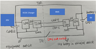
5.Is there any connection between the ground offset of the transceiver and the common mode voltage parameters?