This thread has been locked.

If you have a related question, please click the "Ask a related question" button in the top right corner. The newly created question will be automatically linked to this question.

DS90UB960-Q1: About MIPI's output data late of DS90UB960.

Part Number: DS90UB960-Q1

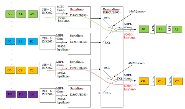
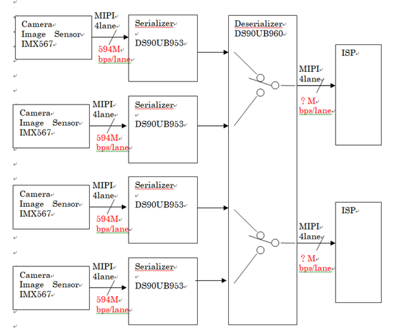
Q1) In case of below the block diagram, can we set 594Mbps/lane of MIPI output at the DS90UB960?


Q2) If we can't set that one of (1), how many data rate "one lane at one CH"   of the DS90UB960?


  • Hi Sugi,

    The 960 CSI-2 transmitter can be configured to 400 Mbps, 800 Mbps, 1.2 Gbps, or 1.6 Gbps per data lane per port. The sum of the input bandwidths to be forwarded must be less than the output bandwidth, so you would need to select a speed that will fulfill this requirement. Can you provide the following information about your system so I can accurately determine what lane speed you will need?

    • Image sensor parameters:
      • Horizontal active pixels
      • Vertical total lines 
      • Frame rate (Hz)
      • Bits per pixel
    • Clock type (continuous or non-continuous clock)
    • Forwarding mode (best effort round robin, basic synchronized, etc.) 

    Regards,

    Cindy

  • Hi Cindy,

    Thank you for replying.

    I answer your questions.

      Note: I answer about one camera. As you know there are 4 image sensors.

    (Ans)
     mage sensor parameters:
       Horizontal active pixels ; 2472pxcels
       Vertical total lines ; 2064 lines
       Frame rate (Hz) ; 15fps
       Bits per pixel ; 12bit
     Clock type (continuous or non-continuous clock)  ; continuous
     Forwarding mode (best effort round robin, basic synchronized, etc.)
       ; I think may be "etc".
                   I want to use DS90UB960-Q1 as only multiplexer. And I chose 1 image sensor with 1 output on DS90UB960-Q1.

                   And I expect the MIPI signals pass through as same data rate on DS90UB960-Q1.

                  Therefore, I expect 594Mbps/lane of DS90UB960-Q1's output.


     Could you please answer below questions.

      Q1) we showed the block diagram, can we set 594Mbps/lane of MIPI output at the DS90UB960?

      Q2) If we can't set that one of (Q1), how many data rate "one lane at one CH" of the DS90UB960?

      Q3) Can I use the DS90UB960-Q1 as only multiplexer?

    Regards,
    Shuichi Sugi.

  • Hi Shuichi,

      Q1) we showed the block diagram, can we set 594Mbps/lane of MIPI output at the DS90UB960?

    You can only set the CSI-2 transmitter speed at certain rates, so 594Mbps is not possible (see section 7.4.19 in the 960 datasheet).

      Q2) If we can't set that one of (Q1), how many data rate "one lane at one CH" of the DS90UB960?

    Based on the parameters for the 4 image sensors, your total input bandwidth sum including CSI-2 overhead is about 3.67Gbps. The equations to calculate this are in section 7.4.20 in the datasheet. 

    If you are using 2 CSI-2 ports with 4 lanes per port, you will need a CSI-2 lane speed of at least 800Mbps per lane to meet the bandwidth requirement (assuming all ports are being forwarded). You just need to ensure that the input bandwidth sum is less than the output bandwidth. 

      Q3) Can I use the DS90UB960-Q1 as only multiplexer?

    If I am understanding your diagram correctly, you want to select either RX port 0 or 1 to be outputted on CSI port 0, and select either RX port 2 or 3 to be outputted on CSI port 1? This should be possible by configuring register 0x20 FWD_CTL1. In this register, you can disable forwarding of any of the RX ports, and you can also map the different RX ports to either CSI port 0 or CSI port 1.

    By default, the forwarding method is best effort round robin in which there is no special ordering of the CSI-2 packets (see section 7.4.25 for more information on forwarding methods).

    Regards,

    Cindy

  • Hi Cindy,

     Thank you for answering for us.

    Cyndy said:
    A1)You can only set the CSI-2 transmitter speed at certain rates, so 594Mbps is not possible (see section 7.4.19 in the 960 datasheet).

    Sugi answered:
    I understand by your explanation.

    Cyndy said:
    A2)Based on the parameters for the 4 image sensors, your total input bandwidth sum including CSI-2 overhead is about 3.67Gbps
    --- skiped ---
    just need to ensure that the input bandwidth sum is less than the output bandwidth.


    Sugi answered:
    I understand by your explanation. So, I'll set 800Gbps/Lane for TX setting.


    Cyndy said:
    A3)If I am understanding your diagram correctly, you want to select either RX port 0 or 1 to be outputted on CSI port 0, and select either RX port 2 or 3 to be outputted on CSI port 1?


    Sugi answered:
    I made more figure. Please see below figure.
    In this case, I want to select either RX port 0 or 1 to be outputted on TX port 0, and select either RX port 2 or 3 to be outputted on TX port 1.
    Do you understand what I explanation by my bad English?

    We have more questions.

    Q4) Our questions are about the relationship between the CIS signal of the serializer input and the deserializer output.

     Q4-1)
    This is explained in the diagram above. Does a relationship correct between "A0, A1, A2" order on the CIS side and "A0, A1, A2" order of the DS90UB960 TX output?

     Q4-2)
    And, does It also correct or incorrect about "C0, C1, C2"?

    Q5)It's about the relationship between "Period of long packet" on CIS signal of the serializer input   and   "Period of long packet" on the deserializer TX output.

     Q5-1) Please see the below figure.
    Can we get below timing chart, if we apply above block diagram and setting registers?

     Q5-2) Is below explanation correct or incorrect? 

    In this case, my understanding is below. ”C period" is shorter than "A period". But "B period" and "A period" are same time. Because we think that the LPS period absorbs the difference between the two data rate. In fact, we need this timing.

    Q6) About memory size.
    How many amount of memory does equipped on the DS90UB960?
     Eg; About 1 Line's Size or about 1 Flame size.

    Regards,

    Shuichi Sugi.

  • Hi Cindy,

     I made a mistake figure last post. I'm sorry.

     Please change a  figure. I mistook a name of signal on time chart. It's output signal of DS90UB960 TX. 

     Regards,

    Shuichi Sugi

  • Hi Shuichi,

    This is explained in the diagram above. Does a relationship correct between "A0, A1, A2" order on the CIS side and "A0, A1, A2" order of the DS90UB960 TX output?

    Yes, packets received on a single input port will be forwarded in the received order. So if you only have one RX port enabled for forwarding on the CSI-2 output, then the packets will be forwarded in the order in which they are received. You can configure the RX port mapping and enabling/disabling in register 0x20.

    And, does It also correct or incorrect about "C0, C1, C2"?

    Yes, same as above answer.

    Can we get below timing chart, if we apply above block diagram and setting registers?

    Your explanation is correct. The deserializer will wait for one full video line to become available before sending the data out at a fixed rate. Since the CSI-2 TX output speed is faster, it will fill the remaining time in the LPS state to maintain the same frame rate. You can refer to this training video for more information: https://www.ti.com/video/6247583604001?keyMatch=

    How many amount of memory does equipped on the DS90UB960?

    The total line buffer memory size is a 16-kB block for each RX port (see Section 7.4.22 in the datasheet).

    Regards,

    Cindy

  • Hi Cindy,

     Thank you for good supporting. So, My questions were cleared by Cindy's. We'll ask you about FPD-LINK again if we have a question.

    Thank you.

    Best Regards,


    Shuichi Sugi

  • Hi Shuichi,

    No problem. I will be closing this thread, but feel free to start a new one if you have any more questions. 

    Regards,

    Cindy