This thread has been locked.

If you have a related question, please click the "Ask a related question" button in the top right corner. The newly created question will be automatically linked to this question.

TUSB213: spec check

Part Number: TUSB213
Other Parts Discussed in Thread: TUSB216I

Hi

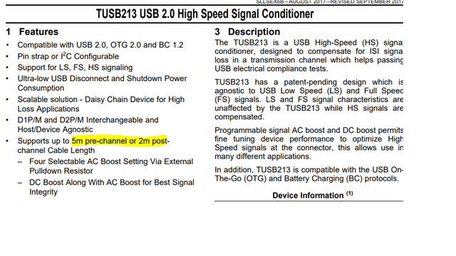
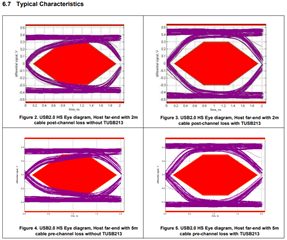
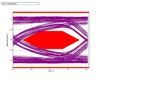
Since there is no eye diagram data of the first 5 meters of the channel in the TUSB213 specification,

can I confirm the actual situation with you? Supports up to 5m pre-channel or 2m post-channel cable length The first 5 meters of the TES test channel → result: Fail

  • Hi Gareth,

    TUSB213 supports 4m pre-channel and 2m post-channel. If you are looking for a redriver that supports 5m pre-channel, I would recommend using TUSB216I for your performance. It supports 5m cable length and it can recover more loss from PCB/cable in the signal. Also, TUSB216I has better jitter performance than TUSB213 and the package allows for both devices (at each end) to be designed.

    Best.

    Josh

  • Hi Josh

    • TUSB213 supports 4m pre-channel →I need to verify whether this statement is valid.
    • If that's the case, I hope you can modify the specifications of TUSB213.

    TUSB213 supports 4m front channel → can you provide the eye diagram data of the front 4m of the channel?

  • Hi Gareth,

    Let me clarify the statement. The amount of loss that the redriver can compensate for usually depends on various factors, so it is hard to give a specific value for how much loss it can compensate for, but from what I can tell, cable length and cable thickness (gauge) would be also considered at this time. It was mentioned that TUSB213 supports 4m when if the gauge is 28AWG. If the gauge is bigger than 28AWG, TUSB213 supports 5m pre-channel. Based on the datasheet, you can meet 5m pre-channel and please refer to typical characteristics in the datasheet for the eye diagram with 5m pre-channel loss with TUSB213.

    Best,

    Josh

  • Hi Josh

    4m pre-channel report result →Fail

    Could you please help confirm if the following test connection method is correct?

    I'm worried about my connection method being problematic.

  • Hi Gareth,

    Could you share the schematic? In the meantime, please double-check that the test fixture is connected to TUSB213 before enable the source to send the TEST_PACKET. You can refer to the test procedure from these app notes (TUSB2XX implementation guide - SLLA392 & TUSB21xx High-Speed Signal Quality Test Modes - SLLA593)

    Best,

    Josh

  • Hi Josh

    The schematic diagram is as follows:

  • Hi Gareth,

    For DCBOOST/ENA_HS pin, pull-down and pull-up resistors don't match with the parameters in the datasheet. Please double-check for DC boost level.

    Have you passed USB TX compliance testing (sending Test_Packet pattern via text fixture as mentioned above)?

    Best,

    Josh

  • Hi Josh

    In actual testing, the resistance values shown in the following figure are used

    But the result also failed.

  • Hi Gareth,

    Which AC boost and DC boost setting are you using?

    Again, I am asking about your test setup. Did you have that the test fixture is connected to TUSB213 before enable the source to send the TEST_PACKET? Have you passed USB TX compliance testing (sending Test_Packet pattern via text fixture)? Most of the issues about eye diagram failure from customers occurred because it was not passed the compliance test. I couldn't approach anything before the test passed since the TX compliance test is the primary checklist.

    Please refer to the test procedure for the compliance test of the app note. (TUSB21x High Speed Signal Quality Test Modes - SLLA593) Also, USB 2.0 High Speed Downstream Signal Quality Testing section of this app note might be helpful to see the test. (TUSB2XX Implementation Guide - SLLA392)

    Best,

    Josh