This thread has been locked.

If you have a related question, please click the "Ask a related question" button in the top right corner. The newly created question will be automatically linked to this question.

TSB12LV32: The internal configuration register “Isochronous Port” stays all 0’s

Part Number: TSB12LV32

Hi Experts,

Good day.

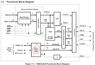
I’m using LLC TSB12LV32 in a new design and during prototype testing we’ve come across the following issue.

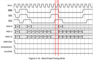
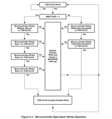
The internal configuration register “Isochronous Port” stays all 0’s when written with a valid “word fixed-timing write” sequence. It is also read by a valid “word fixed-timing read” sequence and shows that the newly written value did not take. The LLC’s MCA pin also acknowledges that the LLC was written or read with a valid set of data. When we perform repeat write/read sequences we notice the value does take after multiple retries. We’ve also noticed that sometimes the upper half or lower half of the word does take in the register while the other half stays 0s. Once the LLC registers are fully set up after multiple retries everything else like data transfer from the MCU to PHY works without any known issues.

  • We have it configured for microcontroller interface fixed-timing mode with a 50MHz crystal oscillator.
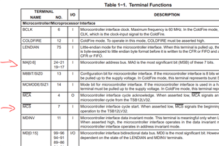
  • We have logic analyzer data that shows proper hold timing from the MCU’s commands to the LLC. We also have o-scope captures that show signal integrity for signals BCLK, MWR, MCS, and MCA being within voltage level and timing tolerance.
  • We’ve also checked the reset signal to ensure the IC wasn’t going into reset between a write and read sequence.

We aren’t sure what the issue is given that everything so far checks out with the given datasheet for this IC.

Please advise


Regards,

Josel

  • This is a very old device; I doubt that any knowledge beyond the datasheet exists nowadays.

    Anyway, what is the behaviour of the busy/pending bits in the Diagnostic register?

  • Hi Clemens,

    We haven’t looked at those. At the moment our code is set up to write to every register in order then after a time (tens of microseconds later) will read from every register in the same order. In order to get a clear register value of 20h will we need to read register 20h after each register write?

    We will need to change our code to read register 20h after every write. This may take some time.

    Also, is there a minimum time required after a write before we can perform another write to another register? I didn’t see this in the datasheet.

    Please advise

    Regards,

    Josel

  • I am reading the datasheet, just like you.

    The description of the busy bits in register 20h says that you must poll them before any write. Other waits should not be necessary.

  • Hi All,

    Good day.

    My group held an internal technical review board meeting on this issue, and we came out with a few questions.

    1. Is there expanded material on what the busy bits actually mean in the Diagnostic Register (20h)? We would like to know how these bits are set and how they are cleared.
    2. What is the maximum time required to clear a busy bit in the diagnostic register after a write-to CFR is performed before another write-to a CFR can be performed? If this does exist, how can we see this in the datasheet?

    Looking forward to hearing what TI has to offer on these questions.

    Please advise.

    Regards,

    Josel

  • Josel

    Isochronous receive packets will be routed to the DM port or the GRF via the receiver routing control logic as shown below, where are you routing the isochronous packet?

    Are you also doing isochronous receive with or without header or trailer?

    Thanks

    David

  • Hi All,

    Good day.

    I don’t understand how your response relates to my recent questions.

    Here is the question rephrased.

    1. Below is figure 3-10 from TSB12LV32-EP datasheet (I’ve added the red lines). Let’s say that address 1 (A1) and address 2 (A2) are CFR’s. Based on the datasheet section “3.3.2 Microcontroller Fixed-Timing Mode” there is no mention that the diagnostic register 20h needs to be pulled (aside what is written out in the actual registry table on page 16) or any timing requirements between two writes. Basically, from a users standpoint of reading section 3.3.2 one would conclude that no additional waits are required to execute a second write to a CFR after a write to a CFR occurred. What is the maximum time after a write to a CFR is required before another write to a CFR can start?


    2. The diagnostic register 20h doesn’t have any timing specification tied to the busy or pending bits (bits 0-7). Without knowing this one would have to assume there could be a chance the LLC could take a billion years to complete a write cycle for the pending bit to clear and the associated busy bit to also clear. Is there a maximum timing specification for how long these actions take?

    Looking forward to hearing back on this topic.

    Please advise.

    Regards,

    Josel

  • Josel

    One quick question, do you have a valid SCLK being provided to TSB12LV32?

    My previous response was regarding this statement, 'the internal configuration register “Isochronous Port” stays all 0’s when written with a valid “word fixed-timing write” sequence,' The isochronous data goes through the TSB12LV32 data move port. I want to make sure the isochronous data is being set up correctly and moving before you read the Isochronous Port register. 

    Also, can you write and read other registers as well?

    Thanks
    David

  • Hi David,

    Yes, the TSB12LV32 has a SCLK signal from the PHY (TSB41BA3 another TI device).

    The hardware isn’t using the Data mover (DM) port. Unless you’re referring to something else.


    We configure the lower half of the Isochronous Port configuration register (bits 0-15), but leave the upper half at power-up reset values 0x0000. As far as I know, the LLC doesn’t function correctly unless the Isochronous Port register is configured correctly first.

    We can write and read other registers as well, however, the isochronous port is the one that doesn’t accept the written value the most often. The others rarely don’t accept the written value.

    Regards,

    Josel

  • Josel

    Let me dig deeper into this Isochronous Port configuration register. By any chance, are you actually receiving isochronous data or just configure the register only? 

    Thanks

    David 

  • Hi David,

    I’ve gathered the following from team members more knowledgeable about communication setup:

    “We configure the control and DM control register in a way that tells the chip to accept and receive messages only when the "channel number" field of the 1394 header matches one of the two values we program into the isochronous port register. We think it is configuring for asynchronous stream data and telling the LLC/PHY to only accept messages when they have the proper channel number in the header. It is the isochronous port register where we define those channel numbers for it to accept.”

    From what I gathered we aren’t sure if we are receiving isochronous data.

    Please advise

    Regards,

    Josel

  • Josel

    Going back to the Microcontroller write operation, based on the write operation flow chart it appears all  4 bytes (byte 0, 1, 2, 3) have to be written before the TSB12LV32 will accept the write. Are you writing all 4 bytes?

    Thanks

    David

  • Hi David,

    Yes, the firmware always writes 4 bytes.

    Please advise.

    Regards,

    Josel

  • Josel

    The 12LV32 does not need to receive isochronous data before updating the Isoch Port register. In fact the register must be written before it can receive.

    But are they actually writing all 4 bytes? The previous response says that "We configure the lower half of the Isochronous Port configuration register (bits 0-15), but leave the upper half at power-up reset values 0x0000."

    Thanks

    David

  • Hi David,

    I agree that the iso port register needs to write to before any iso data is sent which we do follow this logic.

    When I said that I was trying to portray that the lower half change, while the upper half are re-written to 0’s. All 4 bytes are written too. I have logic analyzer captures showing that all four bytes are written too.

    Please advise.

    Regards,

    Josel

  • Josel

    Are they seeing this issue across multiple TSB12LV32 or just a particular TSB12LV32? 

    Thanks

    David

  • Hi David,

    This issue is across all 12 LLCs on the boards I’m working with.

    Regards,

    Josel

  • Josel

    Just to confirm, they are also not seeing the MCERROR interrupt? 

    Thanks

    David

  • Hi David,

    The “MCERRROR” bit looks to trigger the TEA pin.

    We aren’t seeing the “TEA” pin go active to indicate an error during communication.

    Please advise

    Regards,

    Josel


  • Josel

    You have to use the Interrupt/Interrupt Mask Registers at 0Ch and 10h to generate the interrupt at the INT pin. Or you can poll the Interrupt register to see the MCERROR interrupt bit.

    Thanks

    David

  • Hi David,

    I’ve double-checked to make sure the interrupt mask register is set up correctly and it doesn’t change from the default values (0x80001000) which do set MCERRROR to enabled. That’ll trip the TEA signal if an error occurs during communication from the microcontroller.

    As shown in the following logic analyzer pictures the register is set up correctly, but the ISO register isn’t written correctly, and no indication on the TEA pin that a problem occurred.

    The figures are as follows:

    • Failed-ISO_Write_01 – Shows desired ISO port write value 1f140000
    • Failed-ISO_Write_02 – Shows Interrupt Mask write
    • Failed-ISO_Write_03 – Shows Incorrect ISO port value read back as 10140000
    • Failed-ISO_Write_04 – Shows correct Interrupt Mask register values


    The Write_01 picture doesn’t indicate TEA was set which would indicate a failed communication. However, the read in picture Write_03 shows the value wasn’t written to the register.

    I’ve also included the state of the “BUSY bit” in the figures as we programmed it to be shown on STAT1 (which is indicated by the red “1”). It appears to be cleared before the next write is initiated, but the ISO port failed to write and the busy bit for the ISO port appears to be set 1 clock off from MCA which isn’t the case when the write is successful. During successful writes MCA and BUSY bit are set almost at the same time (within 1ns).

    As asked before:

    What is the specification timing requirement around the BUSY bit and its timing relationship with the write/read operation as it isn’t indicated in the datasheet? The only thing that is stated is it needs to be cleared we do have data that shows it’s cleared, but the data still isn’t written to the register.

  • Hi,

    Do you always read back 0x10140000 or does the read value changes? 

    For the logic analyzer capture, is the CLK BCLK or SCLK?

    Thanks

    David

  • Hi David,

    Good day

    The CLK in the logic analyzer capture is BCLK.

    The read value will never change unless a successful write occurs. For testing earlier this week to decrease test time I was flipping between 0x10140000 and 0x1f140000. I switched the byte number when a successful write occurs so I can tell when it fails or succeeds. This way I was able to gain an understanding of the timing relationship of the busy bit behavior before we can perform a write without it failing.

    Please advise

    Regards,

    Josel

  • Josel

    To confirm, if you do the same flipping between 0x10140000 and 0x1F140000 to any other registers, you do not see this issue? 

    Thanks

    David

  • Hi David,

    We do. However, the flipping was only performed on the ISO port to decrease testing time. The other registers we normally write to also exhibit failure to write, but the ISO port register occurs the most often.

    Regards,

    Josel

  • Josel

    The microcontroller pulses MCS low to signal the start of access. Pulsing MCS low for more than one clock cycle enables burst mode. Is it possible that you can try to pulse MCS low for only one clock cycle?

    Thanks

    David

  • Hi David,

    I’m not fully understanding how that would work.

    To my understanding the CFR is a 32-bit register and if we only write the first 16 bits without using burst mode. How will we write to the other 16 bits in the register?

    We are using Microcontroller Fixed-Timing mode to perform the write/reads. There is no easy way to change this.

    Regards,

    Josel

  • Josel

    I was pointing toward the MCADR. The MCADR only needs to contains valid value during the 1st cycle when sample MCCSZ low, I don't know if it is an issue if the MCADR is being sampled with the same value with 2 BCLK cycles. 

    Between each byte write into the CFR register, did you poll the diagnostic register?

    Thanks

    David 

  • Hi David,

    What are MCADR and MCCSZ? I can’t find references to them in the LLC datasheet.

    From the description of the diagnostic register, we found it easier to configure STAT1 to indicate the “Busy Bit’s” status and monitor when it goes low to indicate when the LLC is ready for the next CFR to write. Polling the diagnostic register is the same if not longer amount of time to wait for the “busy bit’s” to clear.

    Please advise

    Regards,

    Josel

  • Josel

    I am referring to MA[0:6[] and /MCS as shown below,

    Thanks

    David

  • Hi David,

    The datasheet doesn’t indicate an issue with keeping the address bits set after the initial cycle when MCS sets low. I’m going to figure it’s okay. TI designed this part so if you have notes that indicate it would be a problem, I’m guessing you could find them.

    Pease advise

    Regards,

    Josel

  • Josel

    This part is pretty old so I am going by what is in its datasheet. The datasheet shows the addr bit only gets clocked only by one clock cycle. I honestly don't know what will happen if the addr bits get clocked by more than 2 clock cycle.

    Thanks

    David

  • Hi David,

    I need to know the specification timing of the busy bits in relation to an MCU write/read access to the CFR. How long should these bits in the register stay set before it clears and when do they set is also unclear in the datasheet.

    Please advise

    Regards,

    Josel

  • Josel

    I do not have the specification timing of the busy bits in relation to an MCU write/read access. The MCU needs to poll these bits before writing to the corresponding byte.

    Thanks

    David