This thread has been locked.

If you have a related question, please click the "Ask a related question" button in the top right corner. The newly created question will be automatically linked to this question.

SN65DPHY440SS: Output level issue

Part Number: SN65DPHY440SS

Hello Expert,

Our customer is evaluatiing and debugging.

Could you please check and give us your opinion?

The part is being used for MIPI signal between Image Sensor and SoC, and the usage specifications are as follows.

-. Interface: MIPI CSI-2 4lane, Datarate: 1.188Gbps, Input Trace: 30cm, Output Trace: 3cm

As for the issue, MIPI signals are not output properly in about 10 out of 40 MAIN BDs manufactured using the part.

The problematic part is the DATA0 line of the part, and the remaining DATA1~3 and CLK are output normally.

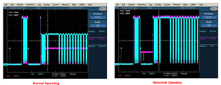
When we checked the signal, the level of the LP signal goes up to 1.2V in B'D where MIPI operates normally.

However, in the abnormally operating B'D, only 0.776V on the INPUT side of Data0 and 0.4V on the OUTPUT side come out.

Therefore, MIPI communication is attempted between the Image Sensor and the SoC, but communication does not seem to be performed properly because the signal level is not matched.

If you need our schematic and top side pcb layout, we can share these.

We would like to be talked privately.

Best Regards,

Michael

  • Michael

    DPHY440’s LP TX is expecting to connect to an unterminated LP RX.  With Lane 0 path (DA0P/N and DB0P/N) supporting bi-directional LP signaling, it is very important that DB0P/N LP TX is connected to an unterminated LP RX.  If DB0P/N LP TX is connected to a HS RX, then LP signaling will not be able to reach the LP11 levels and which will cause the DPHY440 to not enable HS data path on Lane0.

    For workaround, they have to use I2C to enable lane0 HS path:

    Enable HS path for Lane 0 only:

    Write Register 0x50 with 8’h01 //Override enable for HS TX path

    Write Register 0x51 with 8’h01 //HS TX path enabled.

    Write Register 0x61 with 8’h00  // Disable LP path.

    Write Register 0x70 with 8’h01  //Override enable for HS RX path

    Write Register 0x71 with 8’h01  // HS RX path enabled.

    Bit 0 is lane 0

    Thanks

    David

  • Hi David,

    Pls refer to the below our test result and additional symptoms when we checked.

    Could you please write any your comment in line which is our additional symptoms?

    1. Debugging

    1) When the received register setting is applied, the DA0P/N pin goes up to 1.2V normally, but the DB0P/N is the same at 0.4V.

         There is no improvement.

    2. Check for additional symptoms


    a. When we do not apply the setting what you sent, if perform MIPI communication after booting w/ the initial default Image Sensor and SoC communication, it will operate normally. 

        However, the problem occurs when the image sensor is reset again to change the initial setting value of the image sensor.

        At this time, if we do reset the Image Sensor and Re-timer at the same time, the problem does not occur.

        Can you spot any possible problems? Or is there any problem if we do reset the Image Sensor and Re-timer at the same time?

    b. When the symptom of the problem occurred, it was confirmed that after several minutes (almost 3 minutes), the level automatically returned to normal and the image was also output.

        Does the DPHY440 have a function to automatically recover the signal waveform after checking for certain conditions?

        what kind of action is this?

    Best Regards,

    Michael

  • Michael

    Please see my response below.

    1. Debugging

    1) When the received register setting is applied, the DA0P/N pin goes up to 1.2V normally, but the DB0P/N is the same at 0.4V.

         There is no improvement.

    2. Check for additional symptoms

    *** Since we are disabling DPHY LP and only enabling HS through the I2C registers, are you also disabling image sensor and SOC LP and enabling HS only?


    a. When we do not apply the setting what you sent, if perform MIPI communication after booting w/ the initial default Image Sensor and SoC communication, it will operate normally. 

        However, the problem occurs when the image sensor is reset again to change the initial setting value of the image sensor.

        At this time, if we do reset the Image Sensor and Re-timer at the same time, the problem does not occur.

        Can you spot any possible problems? Or is there any problem if we do reset the Image Sensor and Re-timer at the same time?

    *** I would reset image sensor, make sure image sensor comes out of reset, and then reset DPHY440. This will make sure DPHY440 input locks onto valid data.

    b. When the symptom of the problem occurred, it was confirmed that after several minutes (almost 3 minutes), the level automatically returned to normal and the image was also output.

        Does the DPHY440 have a function to automatically recover the signal waveform after checking for certain conditions?

        what kind of action is this?

    *** Please see my first response, if you only enabling HS mode, are you still seeing this condition?

    Thanks

    David