This thread has been locked.

If you have a related question, please click the "Ask a related question" button in the top right corner. The newly created question will be automatically linked to this question.

DP83822HF: Communication with TMS570LC4357 Fast Link Pulse Period Issue

Part Number: DP83822HF
Other Parts Discussed in Thread: TMS570LC4357, HALCOGEN

Hi, I am currently trying to use a DP83822HF as the PHY device in an ethernet set up with the TMS570LC4357 in MII mode in 100Base-TX Full Duplex communication. Currently I am seeing an issue where the timings of periods outlined in the DP83822HF datasheet do not match what I am seeing.

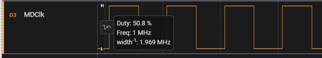
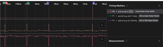
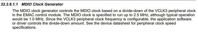
As you can see in the pictures below that I captured using a logic analyzer I am running MDClk at 1MHz (standard clock speed according to TMS570LC43567 datasheet), but for some reason I am getting very strange periods for the Fast Link Pulse from the DP83822HF

I am seeing 16ns for Clock/Data Pulse Width as opposed to 114ns, ~22us for Clock Pulse to Data Pulse Period as opposed to ~62us, ~45us for Clock Pulse to Clock Pulse Period as opposed to ~125

One last note:

I am also only seeing this behavior after power cycling the TMS570. After a clean flash to the TMS570 via JLink Flash or Code Composer Studio debugging session I see standard periods as outlined below in the DP83822HF datasheet, but once I power cycle the TMS570 I start seeing these odd periods.

Any insight on what the issue may be is greatly appreciated

Thanks,

Thomas Hickey

  • Hi Thomas,

    I will take a look and get back to you later next week.

    --

    Regards,

    Hillman Lin

  • Hi Thomas,

    I am not sure if I understand your issue correctly, please correct me if my understanding is wrong:

    • Are you having trouble reading the register of the PHY?
    • Is your MDIO/MDC communication not working for the PHY?
    • Did you have a pull up resistor on MDIO line?
    • Could you probe the voltage of VDDA, VDDIO, VDD1P8?
    • Could you also probe reset pin and Rbias pin voltage?

    --

    Thank you,

    Hillman Lin

  • Hi Hillman,

    I am trying to get the Link Status from the DP83822HF. I have tried reading both the Basic Mode Status Register (register 0x0001) as well as the PHY Control Register (register 0x0019) as I am running in MII mode. The issue I am seeing is that upon flashing my TMS570 I am seeing the Link Status bit being properly set during the MDIO/EMAC initialization process of the TMS570, but if I power cycle the TMS570 & DP83822HF I am no longer seeing this bit being set properly despite not having changed any of the firmware in the TMS570 and never unplugging the ethernet connection.

    It does not seem like I am having trouble reading the register, it just seems as if the Link Status bit is not being set properly.

    The MDIO/MDC communication does seem to be working for the PHY. On the initial flash of the TMS570 everything is able to properly initialize & ethernet communication between the TMS570 & DP83822HF works properly.

    There is a pull up resistor on the MDIO line.

    I can get back to you in regards to the probes.

    The reason I provided images of the Fast Link Pulse signal is because of how the TMS570 reference manual describes the how it detects the Link Status: 

    Thank you,

    Thomas Hickey

  • Hi Thomas,

    I work on the same team as Hillman. He will be OoO for a little bit and his responses will be delayed. I do see that you are having issues with MDC signal. This is an input pin and thus we do not control the timing relating to this signal. This would be a MCU issue. I would recommend taking this up with the TMS team.

    Sincerely,

    Gerome

  • Hi Gerome,

    What issue do you see that I am having with the MDC signal? According to the TMS570 reference manual the typical operation speed is 1 MHz which is what is shown in the logic analyzer capture above.

    Thanks,

    Thomas

  • Hi Thomas,

    I apologize. I misspoke. So to understand your question, you are scoping out the MDIO line and checking the FLP on MDI. So in short, your summarized issue is that you are having link issues correct? Are you able to read register 0x1? What is the value if you read it 3 times?

    Sincerely,

    Gerome

  • Hi Gerome,

    Yes, I am able to read register 0x1. Each time it is read I am reading the value 0x7849.

    Thanks,

    Thomas

  • Hi Thomas, 

    So you are seeing link prior to flashing the TMS, but after you are having issues. Prior to flash the TMS, what are you seeing in register 0x1? Also, is LED_0 active upon link?

    Sincerely,

    Gerome

  • Hi Gerome,

    Sorry for such a late response - I have been out of the office due to being ill the last few days.

    Let me try to explain things a little bit better.

    Currently we are creating a custom board in which we are interfacing a TMS570LC4357 with a DP83822HF for ethernet communications. As it currently stands when we erase & flash the TMS570 with our current firmware we are seeing the EMAC/MDIO modules being initialized just fine, we are seeing the correct bit in the MDIO Link register being set based on communication between the PHY and TMS570, and we are seeing ethernet communication functioning as intended. If we then power cycle the TMS570 (turn off the main power supplied to the TMS570 & then turning back on the main power supplied to the TMS570) we see the EMAC/MDIO modules being initialized just fine, but we are not seeing the proper bit being set in the MDIO Link register & thus a connection is never established between the EMAC/MDIO modules & the PHY. It should be noted that the board has not been re-flashed with new code upon power cycling, we have simply cut power to our board & re-supplied the power.

    The reason that I brought up the FLP timing issue is due to how the link detection is described in the TMS570 reference manual:
     

    It says it uses auto detection to record the current link status, which to my understanding is done through the Fast Link Pulse signal. If I am mistaken & this is not how link status is determined in the TMS570 please correct me. 

    I hope this clears things up a bit. If you need me to provide you with more information such as what we do during EMAC/MDIO initialization process please do not hesitate to let me know. If you are able to provide any information as to why we might be seeing this behavior also please let me know.

    In addition to answer your previous question: 
    1) "Prior to flash the TMS, what are you seeing in register 0x1?"
     - Upon a good link connection (after a fresh erase & flash of the TMS570) in register 0x1 of the DP83822HF I am reading the value 0x786D
     - Upon a bad link connection (after power cycling the TMS570) in register 0x1 of the DP83822HF I am reading the value 0x7849

    2) "Also, is LED_0 active upon link?"
     - We do not currently have any connections on LED_0 or LED_1.

    Thanks,

    Thomas Hickey

  • Hi Thomas,

    Can you share a register dump from 0x0 - 0x1E before and after the power cycle?

    Upon the bad link connection (after power cycling), re-flashing the TMS will fix the issue? If so, what exactly is the flash doing? Is it writing any registers to the PHY?

    Thanks,

    David 

  • Hi David,

    Here are registers before power cycling:

    00> Register 0: 0x3100
    00> Register 1: 0x786D
    00> Register 2: 0x2000
    00> Register 3: 0xA240
    00> Register 4: 0x01E1
    00> Register 5: 0xCDE1
    00> Register 6: 0x000F
    00> Register 7: 0x2001
    00> Register 8: 0x5806
    00> Register 9: 0x0000
    00> Register A: 0x0100
    00> Register B: 0x1000
    00> Register C: 0x0000
    00> Register D: 0x0000
    00> Register E: 0x0000
    00> Register F: 0x0000
    00> Register 10: 0x4015
    00> Register 11: 0x0108
    00> Register 12: 0x6400
    00> Register 13: 0x2800
    00> Register 14: 0x0000
    00> Register 15: 0x0000
    00> Register 16: 0x0100
    00> Register 17: 0x0041
    00> Register 18: 0x0400
    00> Register 19: 0x8C21
    00> Register 1A: 0x0000
    00> Register 1B: 0x007D
    00> Register 1C: 0x05EE
    00> Register 1D: 0x0000
    00> Register 1E: 0x0102

    Here are registers after power cycling:

    00> Register 0: 0x3100
    00> Register 1: 0x7849
    00> Register 2: 0x2000
    00> Register 3: 0xA240
    00> Register 4: 0x01E1
    00> Register 5: 0x0000
    00> Register 6: 0x0004
    00> Register 7: 0x2001
    00> Register 8: 0x0000
    00> Register 9: 0x0000
    00> Register A: 0x0100
    00> Register B: 0x1000
    00> Register C: 0x0000
    00> Register D: 0x0000
    00> Register E: 0x0000
    00> Register F: 0x0000
    00> Register 10: 0x4002
    00> Register 11: 0x0108
    00> Register 12: 0x0000
    00> Register 13: 0x0800
    00> Register 14: 0x0000
    00> Register 15: 0x0000
    00> Register 16: 0x0100
    00> Register 17: 0x0041
    00> Register 18: 0x0400
    00> Register 19: 0x8021
    00> Register 1A: 0x0000
    00> Register 1B: 0x007D
    00> Register 1C: 0x05EE
    00> Register 1D: 0x0000
    00> Register 1E: 0x0102

    After power-cycling flashing the TMS does fix the issue. The flash is just writing a bootloader & main application to the TMS570. The only time PHY registers are written to are either in bootloader or in the main application to initialize ethernet communications.

    These register reads take place directly after auto-negotiation between the TMS570 & DP83822HF (in the case of before the power cycle) & directly after where auto-negotiation would take place if there was a successful link (in the case of after the power cycle)

  • Hi Thomas,

    This is Hillman who will continue debug your current issue on link status bit after power cycle.

    Just want to make sure I understand your issue correctly, please correct me if I miss understand something.

    • Right now, you re-flash the drive on TMS and you are able to see the link status working fine without any power cycle. However, when you did a power cycle, you are seeing the link status bit is not showing link up any more. Am I correct on this statement?

    If I am correct, Can I ask you some question for further debug:

    • Before the Power cycle or when the link status is up, are you able to transfer any packets or frames to the link partner without any problem?
    • After the Power cycle, are you able to transfer any packets or frames to the link partner? I want to see rather it was MDIO issue or MDI issue after power up
    • When you said Power cycle, did you power cycle the whole board or only TMS without power cycle the DP83822 PHY?
    • Could you read 0x0001 multiple times after Power cycle to make sure it is consistence link down after power cycle?

    --

    Thank you,

    Hillman Lin

  • Hi Hillman,

    To answer your questions:

    • Right now, you re-flash the drive on TMS and you are able to see the link status working fine without any power cycle. However, when you did a power cycle, you are seeing the link status bit is not showing link up any more. Am I correct on this statement?
      • Yes, this is correct
    • Before the Power cycle or when the link status is up, are you able to transfer any packets or frames to the link partner without any problem?
      • Yes, before the power cycle when link status is up I am able to both transmit & receive packets just fine
    • After the Power cycle, are you able to transfer any packets or frames to the link partner? I want to see rather it was MDIO issue or MDI issue after power up
      • After power cycle I am unable to transfer packets to the link partner 
    • When you said Power cycle, did you power cycle the whole board or only TMS without power cycle the DP83822 PHY?
      • The whole board
    • Could you read 0x0001 multiple times after Power cycle to make sure it is consistence link down after power cycle?
      • In order to read the status register I am currently using the following function which is generated from HALCoGen:
        boolean Dp83640LinkStatusGet(uint32 mdioBaseAddr,
                                           uint32 phyAddr,
                                           volatile uint32 retries)
        {
            volatile uint16 linkStatus = 0U;
            boolean retVal = TRUE;
        
            while (retVal == TRUE)
            {
                /* First read the BSR of the PHY */
                (void)MDIOPhyRegRead(mdioBaseAddr, phyAddr, (uint32)1u, &linkStatus);
        
        		/*SAFETYMCUSW 134 S MR:12.2 <APPROVED> "LDRA Tool issue" */
                if((linkStatus & PHY_LINK_STATUS) != 0U)
                {
                    /* Check if MDIO LINK register is updated */
                    linkStatus = (uint16)MDIOPhyLinkStatusGet(mdioBaseAddr);
        	
        			/*SAFETYMCUSW 134 S MR:12.2 <APPROVED> "LDRA Tool issue" */
                    if((linkStatus & (uint16)((uint16)1U << phyAddr)) != 0U)
                    {
                       break;
                    }
                    else
                    {
        			    /*SAFETYMCUSW 9 S MR:12.2 <APPROVED> "Ternary Operator Expression" */
        				/*SAFETYMCUSW 134 S MR:12.2 <APPROVED> "LDRA Tool issue" */
        				/*SAFETYMCUSW 134 S MR:12.2 <APPROVED> "LDRA Tool issue" */				
        				if(retries != 0U)
        				{
        					retries--;
        				}
        				else
        				{
        					retVal = FALSE;
        				}
                    }
                }
                else
                {
        			/*SAFETYMCUSW 9 S MR:12.2 <APPROVED> "Ternary Operator Expression" */
                 	/*SAFETYMCUSW 134 S MR:12.2 <APPROVED> "LDRA Tool issue" */
                 	/*SAFETYMCUSW 134 S MR:12.2 <APPROVED> "LDRA Tool issue" */			
        				if(retries != 0U)
        				{
        					retries--;
        				}
        				else
        				{
        					retVal = FALSE;
        				}			
                }
            }
        
            return retVal;
        }

        We pass 0xFFFF as the number of retries, so it is a consistent fail that is happening with the Link Status bit

    Thanks,

    Thomas

  • Hi Thomas,

    From the register dump after power cycle (0x0005), I can see that our PHY is not able to recognize the link partner advertisement. It seems like the link partner is not operating as expected. Have you try reading the link partner to see the status on the link partner side.

    For the link partner, are you able to change it to another DP83822 PHY to see rather there is link up?

    --

    Thank you,

    Hillman Lin

  • Hi Hillman,

    Correct, it is not recognizing the link partner advertisement. It is a bit odd though because our link partner is a PC running Windows 10. We are unfortunately not able to switch it to another DP83822 PHY. Would you be able to give insight as to how the link partner advertisement works? Maybe this would allow us to debug incoming signals to get a better understanding of what is failing on our custom board.

    Thanks,

    Thomas

  • Hi Thomas,

    Link Partner Advertisement will tells the DP83822 PHY what speed they are able to support. In your case, after power cycle, your link partner tells DP83822 PHY that it does not support both 10mbps and 100mbps which result in no link up. Since your link partner is PC, are you able to restart the PC or the PHY inside PC to see rather that help with the issue?

    --

    Regards,

    Hillman Lin

  • Hi Thomas,

    Could you hold the reset button for a long time (around 5s) before you release it while you are power cycling the board to see rather that help with the link up issue? I want to see rather it is the power sequence issue.

    --

    Regards,

    Hillman Lin