This thread has been locked.

If you have a related question, please click the "Ask a related question" button in the top right corner. The newly created question will be automatically linked to this question.

TCA9535: Doubt Regarding TCA 9535 interface with LPC 55S16 Microcontroller

Part Number: TCA9535

Hi,

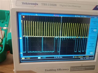
I was using TCA9535(I/O Expander) interface with LPC55S16 microcontroller. We use the I2C communication to communicate with I/O Expander. Set the I2C with given device address,register address and 16 bit data passes through TCA9535.But the I/O Expander can't response with given configuration.

  • Please show the schematic, and tell us what address your firmware is trying to use. An oscilloscope trace would help.

  • Schematic for I/O Expander or 55S16 microcontroller. Below images shows that the our I2C send the Slave address,Register Address,16 Bit of Data to the required Slave(I/O Expander).

  • This is the beginning of a write transaction that looks OK; the TCA9535 responds with the correct ACKs. (So there is probably nothing wrong with the schematic.)

    It's unusual that you use register address 3 to write two (or more) bytes. What are you trying to do? What does actually happen?

  • Hi Vignesh,

    Set the I2C with given device address,register address and 16 bit data passes through TCA9535.But the I/O Expander can't response with given configuration.

    In your statement above, what do you mean by "the IO expander can't response with given configuration?" 

    What response are you looking for from the TCA9535? 

    As Clemens mentioned, this device is correctly ACK'ing. It looks like you are sending the target address followed by the register address 0x03 (output port 1), followed by 0xFF and then another byte of data that is cut off by the o-scope. Are you taking advantage of the auto-increment feature by writing to output port 1 first followed by output port 0? What data are you expecting on the output? 

    Regards,

    Tyler

  • There is no auto-increment feature. I tried to configure and control PORT 1 itself. All the data is properly ACK by the TCA9535. But i not able to see any voltage difference on PINS (all in 0V). 

    Is any need to use INT PIN in TCA9535?

    Also is 1 data frame transfer is enough for single control of PINs or required continuous data transfer?

    We are stuck almost a week kindly navigate in the proper way to achieve the output

  • Did you change the configuration register to set the pins as outputs? At power up, all pins are inputs.

  • I send the configuration of 0X02(also tried 0X03) followed by slave address.

  • The configuration registers are registers 6 and 7. See section 7.6.1 of the datasheet.

  • Thank you for your reply.The configuration part of register was worked very well.And I have a doubt regarding what is the purpose of Output port 0,1 register.(0X03 and 0X04)

  • When a bit in the configuration register is set to 1, the corresponding bit in the output port register is ignored.
    When a bit in the configuration register is set to 0, the corresponding bit in the output port register sets the pin's state.

    The output port registers are 0x02 and 0x03.

  • How to evaluate this register 0X02 and 0X03.?while using this register I not seen any differences in output ports

  • Please show your code.

  • Hi Vignesh,

    There is no auto-increment feature

    TCA9535 supports auto-incrementing, meaning if you read input port register 1, the next port read will be input port register 2. 

    Is any need to use INT PIN in TCA9535?

    INT pin is an external output that can be used by an MCU to tell if an input port on TCA9535 has changed state. This interrupt can then be serviced by the MCU to then read the input port registers that caused the change in order to clear the interrupt. 

    As Clemens has mentioned, configuration port needs to be configured in order to set the p-ports to outputs. It looks like you have already gotten this part working. 

    In order to correctly write to either of the output port registers, you must follow the example in figure 7-7 of the datasheet. 

    This requires a correct I2C slave address to be send, followed by a write bit. The command byte (0x02 or 0x03 for output port registers) is next. Then Data is given to specified port which should set the p-port outputs to either high or low logic. 

    Code would be helpful here, or a scope capture to ensure you are interfacing with the TCA9535 properly.

    Regards,

    Tyler

  • Thank you for your support.