


Part Number: DS90LT012A
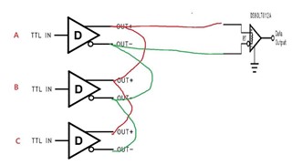
Here you can see the configuration in customer system. There are three diff. line are connected in paralle. Is there possible impedance matching issue?
The A/B/C TTL signal are indepentant.
application: AC inverter
Part Number: DS90LT012A
Here you can see the configuration in customer system. There are three diff. line are connected in paralle. Is there possible impedance matching issue?
The A/B/C TTL signal are indepentant.
application: AC inverter

