Part Number: PSPICE-FOR-TI
Hi,
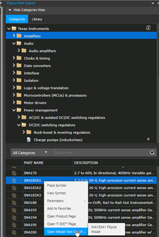
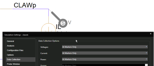
I'm trying to simulate using Pspice for TI, but I'm having trouble running it. The schematic is below.
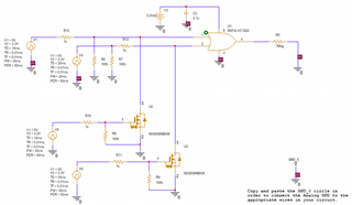
I will send you the error contents in a text file, so could you give me some advice?
--------------- INFO(ORPROBE-3209): Simulation Profile:  SCHEMATIC1-test ---------------
INFO(ORPROBE-3183): Simulation running...
** Profile: "SCHEMATIC1-test"  [ C:\schematic\Pspice\seq\seq-pspicefiles\schematic1\test.sim ]
Reading and checking circuit
Circuit read in and checked, no errors
ERROR(ORPSIM-16583): Detected an imported model containing transistors or diodes. For such models, PSpice for TI supports a minimum of one and maximum of three traces. Reduce the number of traces and simulate again.
ERROR(ORPSIM-16583): Detected an imported model containing transistors or diodes
Run aborted
  Total job time (using Solver 1)   =        1.19

INFO(ORPROBE-3188): Simulation aborted
**** 05/25/23 10:14:10 ******* PSpice 17.4.0 (Nov 2018) ******* ID# 0 ********

 ** Profile: "SCHEMATIC1-test"  [ C:\schematic\Pspice\seq\seq-pspicefiles\schematic1\test.sim ]


 ****     CIRCUIT DESCRIPTION


******************************************************************************


** Creating circuit file "test.cir"
** WARNING: THIS AUTOMATICALLY GENERATED FILE MAY BE OVERWRITTEN BY SUBSEQUENT SIMULATIONS

*Libraries:
* Profile Libraries :
* Local Libraries :
.LIB "C:/schematic/Pspice/nx5008nbkm.lib"
.LIB "C:/schematic/Pspice/sn74lvc1g32.lib"
* From [PSPICE NETLIST] section of C:\cds_spb_home\cdssetup\OrCAD_PSpiceTIPSpice_Install\17.4.0\PSpice.ini file:
.lib "nom_pspti.lib"
.lib "nom.lib"

*Analysis directives:
.TRAN  0 100m 0
.OPTIONS ADVCONV
.OPTIONS FILEMODELSEARCH
.PROBE64 V(alias(*)) I(alias(*)) W(alias(*)) D(alias(*)) NOISE(alias(*))
.INC "..\SCHEMATIC1.net"


**** INCLUDING SCHEMATIC1.net ****
* source SEQ
V_V1         N14941 0
+PULSE 0V 3.3V 10ms 0.01ms 0.01ms 20ms 50ms
C_C2         0 N14671  0.1u  TC=0,0
V_V3         N14671 0 3.3Vdc
V_V4         N14770 0
+PULSE 0V 3.3V 20ms 0.01ms 0.01ms 20ms 50ms
R_R5         N16206 0  1Meg TC=0,0
R_R6         0 N14588  100k TC=0,0
R_R7         0 N14770  100k TC=0,0
X_U1         N16206 N14588 N17183 N14671 0 SN74LVC1G32
R_R8         0 N17264  100k TC=0,0
R_R9         0 N19984  100k TC=0,0
R_R10         N17493 N17264  1k TC=0,0
R_R11         N17813 N19984  1k TC=0,0
V_V5         N17493 0
+PULSE 0V 3.3V 15ms 0.01ms 0.01ms 20ms 50ms
V_V6         N17813 0
+PULSE 0V 3.3V 25ms 0.01ms 0.01ms 20ms 50ms
R_R12         N14941 N14588  1k TC=0,0
R_R13         N14770 N17183  1k TC=0,0
X_U2         N14588 N17264 0 NX5008NBKM
X_U3         N17183 N19984 0 NX5008NBKM

**** RESUMING test.cir ****
.END

**** 05/25/23 10:14:10 ******* PSpice 17.4.0 (Nov 2018) ******* ID# 0 ********

 ** Profile: "SCHEMATIC1-test"  [ C:\schematic\Pspice\seq\seq-pspicefiles\schematic1\test.sim ]


 ****     Diode MODEL PARAMETERS


******************************************************************************


               X_U2.D_DBD      X_U3.D_DBD      X_U1.XU1.D1
          IS    2.096000E-06    2.096000E-06   10.000000E-15
           N    2.475           2.475
          BV   68.8            68.8
         IBV  250.000000E-06  250.000000E-06
          RS    1.000000E-06    1.000000E-06
          TT   18.500000E-09   18.500000E-09
         CJO   83.870000E-12   83.870000E-12
          VJ     .01             .01
           M     .4433           .4433


**** 05/25/23 10:14:10 ******* PSpice 17.4.0 (Nov 2018) ******* ID# 0 ********

 ** Profile: "SCHEMATIC1-test"  [ C:\schematic\Pspice\seq\seq-pspicefiles\schematic1\test.sim ]


 ****     MOSFET MODEL PARAMETERS


******************************************************************************


               X_U2.MINT       X_U3.MINT
               NMOS            NMOS
       LEVEL    3               3
           L  100.000000E-06  100.000000E-06
           W  100.000000E-06  100.000000E-06
         VTO     .8566           .8566
          KP    3.943           3.943
       GAMMA    0               0
         PHI     .6              .6
      LAMBDA    0               0
          IS    1.000000E-24    1.000000E-24
          JS    0               0
          PB     .8              .8
        PBSW     .8              .8
          CJ    0               0
        CJSW    0               0
        CGSO    0               0
        CGDO    0               0
        CGBO    0               0
         NFS  315.500000E+09  315.500000E+09
         TOX  100.000000E-09  100.000000E-09
          XJ    0               0
       UCRIT   10.000000E+03   10.000000E+03
        VMAX    2.133000E+03    2.133000E+03
         ETA    0               0
      DIOMOD    1               1
         VFB    0               0
        LETA    0               0
        WETA    0               0
          U0    0               0
        TEMP    0               0
         VDD    5               5
       XPART    0               0


**** 05/25/23 10:14:10 ******* PSpice 17.4.0 (Nov 2018) ******* ID# 0 ********

 ** Profile: "SCHEMATIC1-test"  [ C:\schematic\Pspice\seq\seq-pspicefiles\schematic1\test.sim ]


 ****     Voltage Controlled Switch MODEL PARAMETERS


******************************************************************************


               X_U1.XU1.SW1    X_U1.XU1.SW2
         RON   10                .01
        ROFF   60.000000E+06  100.000000E+06
         VON    6.5              .55
        VOFF    5.5              .45


ERROR(ORPSIM-16583): Detected an imported model containing transistors or diodes. For such models, PSpice for TI supports a minimum of one and maximum of three traces. Reduce the number of traces and simulate again.


ABORTING SIMULATION
**** 05/25/23 10:14:10 ******* PSpice 17.4.0 (Nov 2018) ******* ID# 0 ********

 ** Profile: "SCHEMATIC1-test"  [ C:\schematic\Pspice\seq\seq-pspicefiles\schematic1\test.sim ]


 ****     JOB STATISTICS SUMMARY


******************************************************************************


Node counts:
  Top level (NUNODS)                =          11
  External (NCNODS)                 =          99
  Total (NUMNOD)                    =         101

Total device count (NUMEL)          =         164
  Capacitors (C)                    =           8
  Diodes (D)                        =           5
  VCVS (E)                          =          58
  VCCS (G)                          =          25
  CCVS (H)                          =           1
  Inductors (L)                     =           6
  MosFETs (M)                       =           2
  Resistors (R)                     =          40
  VSwitches (S)                     =           5
  Voltage Sources (V)               =           8

Number of subcircuits (X)           =          10

Matrix statistics:
  Matrix size (NSTOP)               =         174
  Initial no. elements (NTTAR)      =         427
  No. elements w/ fillin (NTTBR)    =         427
  No. fillins (IFILL)               =           0
  No. overflows (NTTOV)             =           0
  No. LU operations (IOPS)          =           0
  Percent sparsity (PERSPA)         =      98.590

Analysis statistics:
  No. total time points (NUMTTP)    =           0
  No. rejected time points (NUMRTP) =           0
  No. iterations (NUMNIT)           =           0

Load Threads                        =           1

Runtime statistics:                       Seconds      Iterations
  Matrix load                       =        0.00
  Matrix solution                   =        0.00               1
  Readin                            =         .77
  General setup                     =        0.00
  CMI setup                     =        0.00
  Setup                             =        0.00
  DC sweep                          =        0.00               0
  Bias point                        =        0.00               0
  AC and noise                      =        0.00               0
  Total transient analysis          =        0.00
  Output                            =        0.00
  Overhead                          =         .06
  Total job time (using Solver 1)   =        1.19
Thanks,
Conor