This thread has been locked.

If you have a related question, please click the "Ask a related question" button in the top right corner. The newly created question will be automatically linked to this question.

TUSB522P: TUSB522P specification confirmation

Part Number: TUSB522P


Hi, 

Customer would like to double confirm about loss compensation,

1. The maximum loss compensation for channel loss

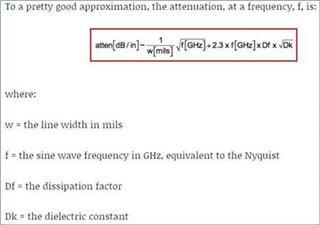
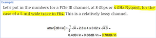
2. According to your previous replied, we can use this formula to calculate PCB insertion loss. Can the values of Df and Dk in example be used for calculation to get loss per inch of TUSB522P (as below). If can’t, could you provide PCB data (used for evaluation trace length of TUSB522P)? 

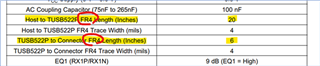
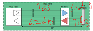
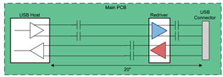
3. The below block diagram shows the total length (pre-channel + post-channel) is 20inch. It is different from the above table. Could you help confirm it?

Best regards,

Randy

  • Randy

    TUSB522P EVM uses FR4 board material, and FR4 has a dielectric constant (Dk) that varies between 3.8 and 4.8 depending on the glass weaving style, thickness, and resin content. You can use 0.02 as the dissipation factor. 

    I sent you an email with a link to the loss calculation, it will be easier to use the spreadsheet to calculate the pre-channel and post-channel length. Please let me know if you need help with the spreadsheet.

    Thanks

    David

  • Hi David,

    Continuation of the question, the insertion loss of TUSB522P is around 0.61dB/inch~0.64dB/inch. According to Design Parameters in datasheet, pre-channel length is 20inches, post-channel length is 6inches. Does it mean the loss compensation of pre-channel and post-channel are 12.8dB and 3.84dB?

    Btw, USB3.1 5G loss budge is 20dB. TUSB522P can recover up to maximum 20dB loss, right?

    Thanks.

    Jack

  • Jack

    The insertion loss of TUSB522P is around 0.61dB/inch~0.64dB/inch ->  the insertion loss of the PCB trace is around 0.61dB/inch~0.64dB/inch assuming we have a trace that has a width of 4mil.

    With 0.64dB/in -> pre-channel of 20in = 12.8dB and post-channel of 6in = 3.84dB.

    Below is the block diagram of TUSB522P RX and TX compensation capability, the remaining compensation needs to come from the USB host and device.

    Thanks

    David

  • Hi David,

    Assuming Host capability is ok.
    Redriver can recover up 9dB (Rx) and 6.2dB (Tx), then using insertion loss of PCB trace: 0.64dB/inch to calculate,

    14inches (Host to Redriver) and 9.6inches (Redriver to device) that are not match the example in datasheet: 20inches and 6inches.

    May I consult how to calculate 20inches and 6inches?

    Thanks.

    Jack

  • Jack

    The insertion loss per in we used for the 20in pre-channel and 6-in post-channel length example is less than the 0.64dB/in. In section 8.2.3 Application Curve example in the TUSB522P datasheet, 

    The pre-channel is 25in that has a -10.5dB loss.

     Thanks

    David

  • Hi David,

    Sorry that I am confusion about TUSB522P compensative capabilities.

    In datasheet Table-1, the EQ can recover 9dB loss. But in section 8.2.3, loss at pre-channel is 10.5dB that still can be recovered.

    In other words, how can designer know if TUSB522P can meet design requirements no matter which PCB materials?

    Pre-channel is 9dB, or 12.8dB, or 10.5dB? And Post-channel is also.

    Thanks.

    Jack

  • Jack

    The TUSB522P EQ can recover 9dB, so with the channel loss being at 10.5dB, there is still 1.5dB loss that can't compensated. And you can see from the eye on the right side that it is still a bit under-equalized. The purpose of section 8.2.3 is to show that TUSB522P EQ can provide compensation and open the closed eye at left to an open eye to the right.

    I sent Randy a spreadsheet which you can use to estimate the pre-channel and post-channel taken the EQ and board loss into account, please ask Randy to set up a call if needed so we can go over the spreadsheet.

    Thanks

    David