This thread has been locked.

If you have a related question, please click the "Ask a related question" button in the top right corner. The newly created question will be automatically linked to this question.

SN65HVD233-HT: RS Line Troubleshooting

Part Number: SN65HVD233-HT

Problem Statement

A high rate of failure has been observed while using the SN65HVD233SHKJ transceiver chip in one of our designs. The characteristics of failure appear to be the same on most failed parts, detailed below.

Here's our circuit:

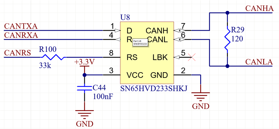
CANTXA and CANRXA are connected to their respective pins on the processor. CANRS is connected to a GPIO and is always pulled low.

Observations

  • During high temperature testing, some of our devices will cease to communicate over CAN bus. The temperature at which this happens varies (70C to 160C), and it only happens to some parts. We have seen some correlation between transceivers failing, e.g., a batch of three all failed at the same time during a high temperature cycle. All three devices were on independent CAN busses during testing.

  • During this failed state, data from the CAN bus is successfully translated to logic levels and output on the R pin of the transceiver chip

  • The processor successfully interprets the data and sends a corresponding ACK signal to the D pin of the transceiver chip

  • The ACK signal does not make it onto the CAN bus, the transceiver chip does not drive the bus to the “dominant” state

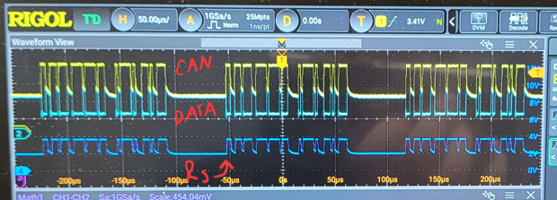
  • On faulty transceiver chips, the Rs pin appears to have CAN data, as seen in the scope capture below. Note that we use a 33kOhm resistor from Rs to ground, indicating that the Rs pin is sourcing about 60uA to generate about 2V on the Rs pin (when there’s no CAN traffic). If we short the Rs pin to ground (bypassing the 33kOhm resistor), the chip starts working as expected. When shorting the Rs pin to ground, it sinks about 395uA.


  • On good transceiver chips, the Rs pin generates a steady 1.1Ve across a 33kOhm resistor to ground, indicating that the Rs pin is sourcing about 33uA. When shorting the Rs pin to ground on a good transceiver, the chip sinks about 268uA.

Questions

  1. Do our observations indicate that the transceiver chip is damaged? If so, what might be causing the damage?

  2. Omitting the resistor on Rs and connecting it to ground causes these failed parts to operate. Is this a valid long-term solution?

  • Nathan,

    First, thank you for all the information to start with this debug. From your description, it does indeed sound like damage is occurring, though I have a few more questions.

    1. Yes, it seems like Rs is getting damaged in some way and a leakage path is being created. The fact that Rs is following CANH, the pin adjacent to it, means some kind of short is occurring internally or externally. Can you verify no solder shorts after the temperature testing? It doesn't seem likely, but I wanted to check that first. 

    2. What's happening here is that the leakage path created by whatever damage is occurring to the Rs pin is not allowing it to pass the lower threshold for fast mode with the 33k ohm resistor, as you've observed. This is also causing the D pin to not pass any data to the bus because the device sees the state of Rs as the higher threshold and thus goes into low-power mode. 

    In your description you say Rs is 33k to GND, but in the schematic it is connected to something, is this a controller? Also, can you give more details of what is happening in your temperature cycle testing to the transceiver? Is it just CAN communication? Is the anything else "special" occurring that may introduce voltage transients?

    Regards,

    Eric Hackett 

  • Eric,

    Please see my response below:

    1. Yes, our first thought was that some kind of short between RS and CANH was happening, but we were very puzzled to find that the impedance between those pins was identical between boards that exhibit this issue and boards that do not exhibit this issue. Additionally, we followed the signal paths on the board to see if we could visually find anything, but everything looked clean.

    2. That makes sense -- that's about the theory that we came up with as well. We have some theories on what might be causing that damage on the RS pin, but we have not been able to conclusively pinpoint the root cause.

    Yes, after that 33k Ohm, the RS line goes to a GPIO. At some point, we had considered wanting to have some control over the state of RS, but we never implemented the firmware for it and likely never will -- the GPIO is always pulled low and never changes state.

    There's nothing really special going on during the temperature cycle -- the processor collects sensor measurements and puts them on the CAN bus and that's about it. We don't do any kind of power cycling during these temperature cycles or anything else that I can think of that would induce a voltage transient.

  • Nathan,

    Thanks for the additional replies.

    1. I'm a little confused, in your first post you mention a higher current draw on the Rs pin with a device exhibiting the damaged behavior, but you don't measure a different in impedance on the pins? And there has to be some kind of path between Rs and CANH, the data is following it exactly. But does this behavior disappear when Rs is shorted to GND as well as the device functioning normally?

    2. Yes, this seems to be what is happening. What theories do you have for the damage?

    This is a strange case, especially since the temperature cycling is within range of the device's qualification, and I'd expect damage, if anywhere, to occur on the CANH and CANL pins. Can you check CANH and CANL impedance to GND and to VCC and compare it to a known good unit? 

    Regards,

    Eric Hackett