Hi Team,
Please provide a below thermal details
- Recommended Operating Junction Temperature Range
- Maximum Allowed Case Temperature Limit (°C)
- junction-to-case (bottom) thermal resistance (°C/W)
This thread has been locked.
If you have a related question, please click the "Ask a related question" button in the top right corner. The newly created question will be automatically linked to this question.
Hi Team,
Please provide a below thermal details
Hi Priyadharshini,
1. Rec. Operating Junction Temperature range - No rec. spec'd. keep junction temp < 150C - don't operate part beyond ambient temperatures listed in rec. operation (depends on device suffix which temp range is used - C is 0C to 70C and I is -40C to 85C - junction temperature should never be below 0C and -40C respectively for C and I devices based on rec. operating temperature range (any power is going to increase temperature beyond ambient -so below those limits is not recommended for normal operation)
2. TC max: That is application specific - we can't tell you that; the thermal information provided in teh datasheet along with the testing of your system will determine that. Please note that thermal impedances are affected by the system parameters so those values are apt to change in use due to the system around it.
3. junction to case (bottom) - Since these parts do not have a bottom thermal pad this spec isn't specified - this spec is only specified for devices with thermal pads on the bottom of the IC.
Best,
Parker Dodson
Hi Parker,
Thanks for the information
Please provide power consumption/ dissipation for Max3232E
HI Priyadharshini,
Power dissipation isn't directly spec'd on this device.
The typical power dissipation (no load; VCC = 3.3V to 5V) is going to be based on the ICC current - which under the previously mentioned test conditions is between 300uA and 1mA - so typical at 5V with no load is 1.5mW and it can go up to 5mW - if you power with 3.3V the max no load power is going to be 3.3mW. Adding additional loading is going to increase power consumption as the current at the outputs are sourced from VCC.
Best,
Parker Dodson
Hi Parker,
Could you tell the maximum current value that driver can supply while it working with load
Hi Priyadharshini,
The device has limited short circuit protection - so the maximum current the device will output is +/-60mA under a short condition - but this is typically capped to +/-35mA.
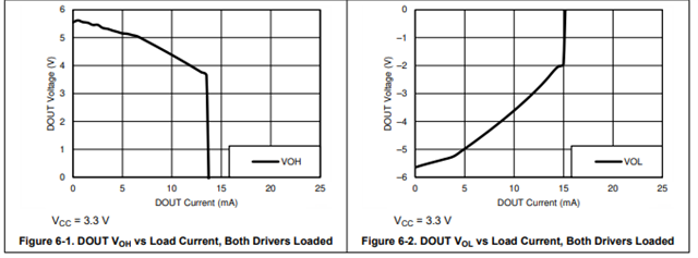
Under normal operation conditions the minimum load should be no less than 3K - its minimum VOUT is 5V - so the max current under worst case - but under rated condition operation is going to be about 5/3K -> 1.67mA typical. You really probably shouldn't be drawing too much more out of the device under normal operation. That being said - we do have a Voltage versus output current graph in the datasheet that gives an idea of the current output for a typical device.

For a VOH (output high) we seem to clamp an output current right around 13mA to 14mA and about 15mA for VOL. However to keep compliant with RS-232 the VOH and VOL magnitude need to be 5V or greater so that really is < 5mA of current - but under RS-232 bus design you really shouldn't be seeing > 2mA.
Best,
Parker Dodson
Hi Parker,
Thanks for the information,
Could you please suggest a recommended switching frequency for the power regulator to be used with this part
Hi Priyadharshini,
If possible its always good to put an LDO after the switching regulator to clean up the signal - this isn't practical in every system; but ideally that will get the cleanest power signal.
That being said
We don't have a specific recommendation as we generally assume The VCC voltage will be operated at either 5V +/-10% or 3.3V +/-10% - so ripple voltage is more important than switching frequency and we assume that the regulator output bulk capacitance and bypass capacitance will reduce ripple to be within recommended operational bounds.
As long as the supply + output filtering can:
1. provide low ripple voltage (within 10% of 5V or 3.3V throughout its period)
2. Provide enough current to run device (most switched mode power supplies aren't going to have a major issue here - but it is important to check)
Then it will probably work okay - the cleaner the signal the better but really the power supply chosen is more based on your needs from the power tree itself. I.e. slower switching regulators use bigger passive components but are generally have less emissions issues where faster switching regulators are smaller because of smaller passive components but layout becomes more important due to higher risk of unwanted emissions.
Best,
Parker Dodson