This thread has been locked.

If you have a related question, please click the "Ask a related question" button in the top right corner. The newly created question will be automatically linked to this question.

SN65DSI83: Resolution and color problems

Part Number: SN65DSI83

Hi,

We are working whit a custom board based on the imx8mp that has the SN65DSI83 used to connect a LVDS display to the SOC. The OS has been generated using Yocto hardknott and the NXP BSP. We are using the kernel version 5.10.72. 

The register values we are using are:

Register      Value
0x0D          0x00
0x0A          0x05
0x0B          0x10
0x10          0x20
0x12          0x11
0x18          0x78
0x19          0x02
0x1a          0x02
0x20          0xE0
0x21          0x01
0x24          0x10
0x25          0x01
0x28          0x10
0x29          0x00
0x2C          0x04
0x2D          0x00
0x30          0x04
0x31          0x00
0x34          0x2b
0x36          0x0c
0x38          0x08
0x3A          0x08

The connected display has 480x272 pixels resolution and the display parameters showed in the datasheet are:

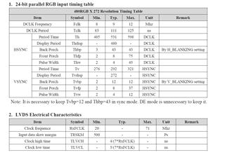
The LVDS clock frequency we measure on the side of the display is 28960000 Hz.

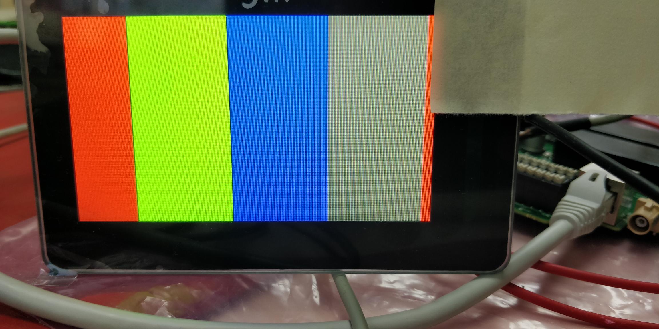
The resulting image is:

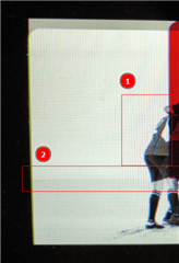
In the point 1 the edges should be white but it is painted in blue color.

In the point 2 there this a color change horizontally which is not in he original image.

Is there an incorrect value stored in any of the registers?? What parameters can affect what is shown in points one and two of the image above?

Regards,

Gustavo Plaza.

  • Gustavo

    Looking at the panel spec, is my understanding correct that the DCLK is the DSI83 LVDS clock frequency that needs to be outputted to the panel? If this is the case, then the DLCK frequency is outside the DSI83 LVDS clock supported range. The minimum LVDS clock frequency DSI83 can support is 25MHz. 

    Thanks

    David

  • Dear David, thanks for your prompt response.

    Our screen has an LVDS to 24bRGB adapter embedded. We are interfacing the SN65 to the LVDS signals that must be between 20MHz and 71MHz, so this should not be an issue for the SN65. Or that's what we think...

    I have included the 24-bit RGB information because there we can find the information for the HSYNC and VSYNC configuration.

    Is there an incorrect value stored in any of the registers?? What parameters can affect what is shown in points one and two of the image above? 

    Thanks and kind regards.

  • Gustavo

    Did you use the DSI Tuner SW to generate the register programming value? 

    0458.DSI-Tuner.zip

    If you enable the DSI86 internally generated test pattern, are you seeing the same issue with the test pattern?

    Thanks

    David

  • Hi David,

    I attach the generated the using the DSI Tuner SW, but applying this values to the registers, the image color is no correct.

    //=====================================================================
    // Filename   : CSR_dsi.txt
    //
    //   (C) Copyright 2013 by Texas Instruments Incorporated.
    //   All rights reserved.
    //
    //=====================================================================
    0x09              0x00
    0x0A              0x01
    0x0B              0x10
    0x0D              0x00
    0x10              0x26
    0x11              0x00
    0x12              0x11
    0x13              0x00
    0x18              0x78
    0x19              0x00
    0x1A              0x03
    0x1B              0x00
    0x20              0xe0
    0x21              0x01
    0x22              0x00
    0x23              0x00
    0x24              0x00
    0x25              0x00
    0x26              0x00
    0x27              0x00
    0x28              0x21
    0x29              0x00
    0x2A              0x00
    0x2B              0x00
    0x2C              0x04
    0x2D              0x00
    0x2E              0x00
    0x2F              0x00
    0x30              0x04
    0x31              0x00
    0x32              0x00
    0x33              0x00
    0x34              0x2b
    0x35              0x00
    0x36              0x00
    0x37              0x00
    0x38              0x00
    0x39              0x00
    0x3A              0x00
    0x3B              0x00
    0x3C              0x00
    0x3D              0x00
    0x3E              0x00
    
    
    The PLL_EN bit and SOFT_RESET bit are not set as they need to be set per the recommended sequence defined in the datasheet

    When I activate the test pattern using the register 0x3C, the display shows the following image:


    I don't kwon where the problem can be, if the DSI is not correct or the DSI83 register configuration is not correct.

    Do you think incorrect values are stored in any of the registers for this specific display? What parameters can affect what is shown in points one and two of the image above? 

    Thanks and kind regards.

  • Hi Gustavo, 

    What is the DSI clock frequency on the DSI83 input? 

    Thanks, Allison

  • Hi Allison,

    The DSI clock frequency is 86.88 MHz

    Thanks and kind regards.

  • Hi Gustavo,

    The register configuration seems to be correct. Are you following the initialization sequence outlined in table 7-2 on the datasheet?

    Thanks, Allison