This thread has been locked.

If you have a related question, please click the "Ask a related question" button in the top right corner. The newly created question will be automatically linked to this question.

AM26LV32E: The receiver chip will burn out during the inter-board communication between the AM26LV32E receiver and the AM26LV31 driver interface chip. And the board is hot.

Part Number: AM26LV32E
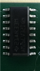
Other Parts Discussed in Thread: AM26LV31, , STRIKE, AM26LV32

1. The receiver chip will burn out during the inter-board communication between the AM26LV32E receiver and the AM26LV31 driver interface chip. And the board is hot.
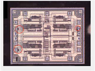
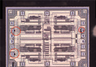
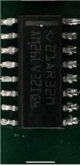
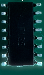
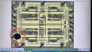
2. During our use, the receiver differential input fusing phenomenon occurs (it can be clearly seen after the chip is opened); A similar phenomenon occurs with driver AM26LV31, but driver AM26LV31 is less likely to have problems than receiver AM26LV32E.
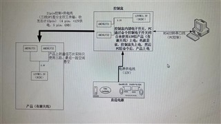
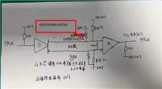
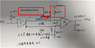
3. When using, the plates are interconnected by differential lines about 2m long, and no resistors are connected in series on the lines; The chip is powered by a 12-to-3.3 DCDC, a differential pair termination resistor of 120Ω, and an 825 ohm pull-up configuration on the receiver differential pair. Each terminal of the chip is pulled up through a 10k resistor and directly connected to the FPGA.
4. The receiver does not do any ESD protection circuit.
After the fault, we monitored the differential input and power supply on the normal board for a long time, and did not get a relatively abnormal signal!

We want to know why this chip is fusing? Or is it possible to guess the possible cause of failure or give us some suggestions for troubleshooting according to the internal circuit of the chip? Are there any suggestions to help us avoid this failure?

  • Hi Aiwen,

    Can you send me the top picture of one of the units -I want to look at the part markings to trace the device in our system to verify if they are legitimate devices.

    Essentially I am not sure why you are seeing these issues in the system - nothing with how you have the system setup seems to be an issue - but what voltage levels are you holding G or /G at? There are points where you can increase the current through the chip that could cause excessive heat - but that is really the only thing that I could see. 

    Have you ensure that there are no shorts between wires or direct shorts to power supplies? As if enough channels are shorted you could increase the junction temperature quickly ending in a burned out device. 

    Please let me know!

    Best,

    Parker Dodson

  • This is the silkscreen of the chip,In addition to short circuit, are there other reasons for this problem?  ESD protection? or  other  reasons?

    At present, sometimes the driver chip will be burned, and sometimes the interface chip will be burned, but the probability of two chips burning out at the same time is very small, and the general situation is that the interface chip burns out. The customer replied that there was no short circuit in the circuit. Replace the burnt out chip with a new one, and the system will work normally again. 

    accroding  to  following  picture,What burns out is basically a differential line。Can you help analyze what factors can cause this problem?

    I suspect that the clamping voltage of the ESD device is too low, or that the 825Ω resistor shown in the diagram is too low. Will these two factors affect the burnout of the interface chip?  In  this  picture,I  find There are no other protection measures in the circuit, does this pose a hidden danger to the entire circuit?

    Do you have any better suggestions to solve this problem?

  • Hi Aiwen,

    I have a strong suspicion this part is counterfeit - the parts markings don't point to the device that is being used. Please see this information for next steps: https://www.ti.com/support-quality/quality-policies-procedures/anti-counterfeit.html 

    I think the biggest issue is the suspect part - in general choosing more robust diodes would help protect the device under harsher ESD strikes - but if the device is counterfeit I can't be certain if anything actually needs to change in the design (except the removal of counterfeit device). Nothing on your schematic should be creating this issue - if the ESD strike is too big than add more robust ESD diodes -but the counterfeit suspicion is the biggest issue.

    Best,

    Parker Dodson

  • Hi Parker;

    Thank you for sharing, I am confirming the fault situation with the customer and letting the customer provide the corresponding device.

    In addition, one of the phenomena is that every time the interface chip is burned, the GND of the RS422 to serial port line that we communicate with the PC has a direct burning phenomenon. Do you have any suggestions?

    The 422-to-serial port line on the PC side is also directly connected to the communication chip (AM26LV32/31), and the basic circuit is the same; But the working voltage of the standard communication line is 5V, and the operating voltage of the interface chip we use is 3.3. This theory should not have a relatively big impact, please know this difference. Can you help analyze the reason? Thank you!

  • Aiwen,

    If the part is counterfeit  - which it seems to be - the supply needs to be corrected - there is no solution that will work with the counterfeit device. The link I provided above are the next steps - there is really nothing else I can do to support at this point unfortunately.

    Best,

    Parker Dodson

  • Hi  Parker;

    There is another problem, we use the power supply to directly rush into the receiver at a given voltage, directly from 0V to 28V is fed from an external machine cable, and the current limit is 0.5A。At around 28v, the chip is damaged, and then we take the damaged chip out of the cover, and we find that the differential pins shown in the figure are damaged. Whats  the reason?thanks!

  • Aiwen,

    The max voltage at the receiver is 14V - you doubled that value - I am surprised it lasted to up to 28V as its not rated that high. The die could not handle the energy flowing through it at 28V - regardless of current (but 500mA is still a lot of injected for RS-485 devices which are limited to 250mA) 

    Best,

    Parker Dodson