This thread has been locked.

If you have a related question, please click the "Ask a related question" button in the top right corner. The newly created question will be automatically linked to this question.

DP83TG720S-Q1: Remote Wakeup using Send-T pattern, INH pin status

Part Number: DP83TG720S-Q1

Hello Team, 

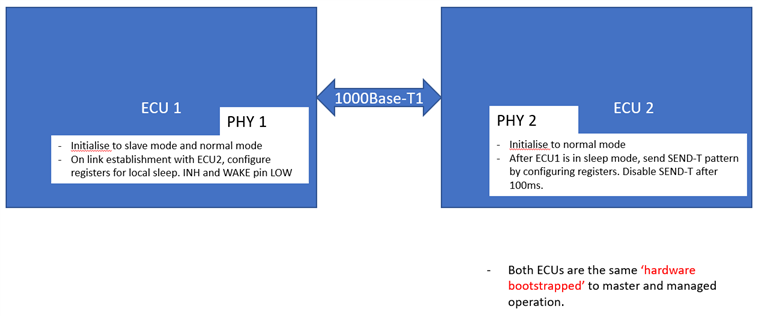
For a customer project, we have used the DP83TG720S-Q1 Ethernet PHY for 1000Base-T1 communication on the ECU board. The bootstrap configuration are in Master Mode and managed mode. We wanted to experiment on the sleep/wake-up functionality. 

For a local or remote wake-up, the INH output pin, when triggered transition high will enable the PMIC connected and turn the power supply for the PHY and the PHY transitions to normal mode(since it is bootstrapped to managed operation)

Please correct me if I am wrong in my understanding in the below statements

1) For a local wake up, the wake pin triggers the INH pin

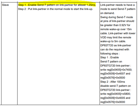
2) For remote wake up, the send-T pattern from remote link partner will trigger the INH pin due to the energy detection on the MDI 

We want to test the sleep/wake-up functionality using two of our ECU boards. Since, the bootstap configuration is Master, we want to change one of the ECU PHY's to slave. We were able to achieve this by setting the register 0x1834 = x8001 for slave mode. 

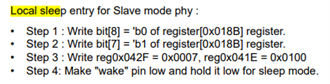
My query is when we put one of the ECUs to sleep(configured to sleep mode, using local sleep steps), 

3) should we enable the energy detection bit in register 0x018B when following the steps for local sleep, if we want to later wake it up using remote wake up by remote- link partner?

4) if enable detection bit is set i.e the above step done before it goes to local sleep, for remote wake-up the send-t pattern is sent by remote link partner(master mode) will the local ECU(sleep mode) have the INH pin triggered high on send-t pattern? Or should the wake pin also be set high in the local ECU? Are there any other requirements?

5) Sometimes, when sleep mode is activated, and we transition back to normal mode, the register values are lost(as mentioned in the manual). If we do a hardware reset via register access(0x001F = x8000), the values do not reset to default values. Is there any reason for this? Or any script we can use to initialise the registers back to default value?

Looking forward to your response.

Thanks in advance

Aarathi

  • Hi Aarathi,

    1. Correct
    2. Correct
    3. No. Section 7.4.6.3 of the datasheet describes the Normal to Sleep transition. No additional write is needed. Remote wake up will still be possible.
    4. An asleep PHY can be woken either locally or remotely. See section 7.4.6.4 of the datasheet.
    5. All register configurations are lost in sleep mode. This means they will reset to default values. No hardware reset is needed. 

    Thanks,

    David

  • Hi David,


    Thank you for your response. I understood the points you mentioned.


    I am not able to perform a remote wake-up. I will explain the steps to give you a better picture. Maybe there is something I have missed.


    As shown in the diagram below. ECU 1 and ECU 2 have the same hardware design.

    As they are hardware bootstrapped, slave mode configuration via register access is in needed.

    As well as the transition from standby to normal mode via register access due to managed mode bootstrap.


    Also, we are focussed on the INH pin, transitioning to low and high. The INH pin is not connected to a PMIC currently. Once we see that the pin transitions we manually trigger(on/off) the power supply for the VDD1P0. VDDIO, VDDA


    For ECU 1, the following steps are performed:


    • Initialise to slave mode: 0x1834 = 0 x8001
    • Initialise to normal mode: 0x018C= 0x0001


    Link is established with ECU2.


    Then local sleep for ECU1


    On wake pin going low, we can see that the INH pin goes low. We then turn the pin for power supply(similar to the PMIC) off.


    For ECU2, the following steps are performed:


    • Initialise to normal mode : 0x018C = 0x0001


    Link is established with ECU1


    After local sleep in ECU1, ECU2 remote wake up as remote link-partner are performed


    • Step 1 is done. On sending the SEND-T pattern we should observe the INH go high. Unfortunately I am not able to see that


    Is there any step missing? Or are there any possible suggestions as to why ECU1 may not be waking up.


    I can locally wake up ECU1, by setting the wake pin high.


    Thanks and Regards

    Aarathi

  • Hi Aarathi,

    Can you probe the line after you enable Send-T on the link partner? I would like to see if there is energy on the line after performing the writes. Note that 0x405, 0x509, 0x576 are extended registers so you must use the procedure listed in section 7.4.11 of the datasheet.

    Thanks,

    David

  • Hi David, 

    Unfortunately, we do not have the equipment to probe the line. But we are looking to purchase one. Please can you confirm the frequency range for transmission and reception, because in the datasheet at certain sections, it show 750 MHz, 125MHz, and 25MHz pattern.  

    Yes, the mentioned registers in the above reply are accessed accordingly as extended registers. 

    Thanks and Regards

    Aarathi 

  • Hi Aarathi,

    The master mode link-partner will start Send-S signals to start the link-up. We can restart the link up process by writing 0x1F = 0x4000 on the master mode PHY. Please try this write and let me know if the slave side PHY wakes up. 

    I am not sure what you mean by "the frequency range for transmission and reception", could you clarify this?

    Thanks,

    David