Hi,
I am trying to use the IO expander chip PCF8574A to READ ports P5-P7.
I do not have any devices connected on these ports, the pins are just pulled up or pulled down so that they return either 1 or 0 (these help with binary patterns for identifying different boards)
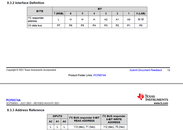
I understand from the datasheet that the device should be given a control address of 0x71 if A0, A1, A2 are grounded and then the device responds with the data P0-P7.
I have been struggling with these for the past few months and now it turns out that the device is responding to 0x38 which is its slave address. When using 0x71 there is either no response at all or P0-P7 appear zero consistently even if some of the ports are pulled up.
I am confused as to how the datasheet can be giving such wrong data.


Question: Is this a known issue?
I just want to make sure I am using the chip in the right way. I can read the data correctly now however the inconsistency with the datasheet is worrying.
Regards,
Rashmitha

