This thread has been locked.

If you have a related question, please click the "Ask a related question" button in the top right corner. The newly created question will be automatically linked to this question.

DS90UB948-Q1: Software configuration.

Part Number: DS90UB948-Q1
Other Parts Discussed in Thread: ALP

Hi team,

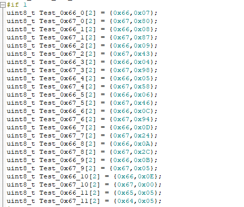
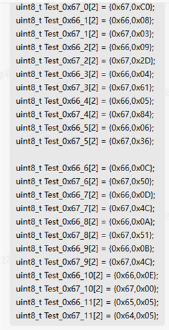
The customer use 948 for splitter mode. And their configuration is as below:

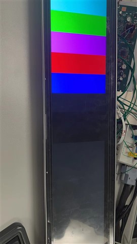
But the second display can't show any image and the first display works normally as below. Could you explain the reason? Or could you tell me how to troubleshoot this problem?

  • Hi Kate,

     It's from another customer question. These are 2 irrelevant problem.

  • Hale,

    Thanks for the update. I just wanted to make sure. Would you be able to send me more info about the system/a block diagram? What is your objective for using splitter mode here?

    Thanks,

    Kate

  • Hi Kate,

    The customer's application is like cluster and control display with two fpdlink 948. Now the cluster can show picture and the control display can't work. And the customer replied that if they configure 948, the control display can't work. And if they use SER to try communicate with 948, the control display can work normally. So we think that the customer 948 configuration is wrong. Could you help check their 948 configuration with control display?

    Below is their report. There are 2 question:

    1、As I talked before, you can check 2 fpdlink configuration but the control display can't work while it can work with 941 to configure.

    2、When writing the 948 register, the value measured on this side of the waveform is written with data, but when the host reads 948, it is found that the read data is the default. Why? Is there any similar situation?

    Report.pdf

  • Hi Hale,

    Thank you for the info. I'll look into it and get back to you in 1-2 days.

    Thanks,
    Kate

  • Hi Kate,

    Is there any progress?

  • Hi Hale,

    Please take a look at Section 7 of this document for configuration guidance.

    snla308a (1).pdf

    Thanks,

    Kate

  • Hi Kate,

    This question is not about splitter mode. Did you check software configuration? Now the customers are not sure if the configuration is right for pattern mode. They referred to file (https://www.ti.com/lit/an/snla132g/snla132g.pdf?ts=1686646413646&ref_url=https%253A%252F%252Fwww.ti.com%252Fproduct%252FDS90UB948-Q1 ). But the clock is wrong. We think that the clk configuration is wrong. Please help check if there is anything wrong about clk.

  • Hi Hale,

    I see now. Sorry for the confusion. What are you using for your V/H back porch, front porch, and sync?

    You can verify what the 948 is getting using this resolution dump script:

    import time
    UB948 = 0x58
    time.sleep(1)
    board.WriteI2C(UB948,0x68,0x19) # H active High monitor
    Hhigh = board.ReadI2C(UB948, 0x69, 1)
    board.WriteI2C(UB948,0x68,0x09) # H active Low monitor
    Hlow = board.ReadI2C(UB948, 0x69, 1)
    board.WriteI2C(UB948,0x68,0x39) # V active High monitor
    Vhigh = board.ReadI2C(UB948, 0x69, 1)
    board.WriteI2C(UB948,0x68,0x29) # V active Low monitor
    Vlow = board.ReadI2C(UB948, 0x69, 1)
    mask = int('00111111',2)
    hlowmask = Hlow & mask
    hhighmask = Hhigh & mask
    vlowmask = Vlow & mask
    vhighmask = Vhigh & mask
    hhighmask = hhighmask << 6
    vhighmask = vhighmask << 6
    Hactive = hhighmask | hlowmask
    Vactive = vhighmask | vlowmask
    print Hactive ,"x", Vactive  #print out detected Dimensions

    You can use this to verify if the 948 is getting the proper timing.

    Thanks,

    Kate

  • Hi Kate,

    Thanks.

    About the spec, you can check this report.

    4478.Report.pdf

    And as for your resolution dump script, how can I tell 948 is getting the proper timing? What result will I get if the clk configuration is wrong?  And I think that the clk configuration must be wrong because we test the clk pin. So what register do we need to modify to get right clk?

  • Hi Hale,

    You only have blanking listed on the report, not back porch, front porch, and sync. The resolution dump script will dump out the timing parameters that the 948 is receiving. This can then be compared to the specs you're using, so that you can verify if the timing the des is receiving is correct.

    Thanks,

    Kate

  • Hi Kate,

    I will talk about with the customer and get more information.

    But why do I need to make sure if the timing the des is receiving is correct? We have configured the register. But the CLK is wrong, and I think that we need to check if there is any error about this configuration or there is any register we still not configure.

  • Hi Hale,

    Let me clarify. The timing specs determine the PCLK, which directly translates to the rate of your CLK pins (more on this can be found in Section 7.4.1 of the datasheet). You need to ensure that the deserializer is getting the proper timing parameters, otherwise your PCLK won't be correct.

    Thanks,

    Kate

  • Hi Kate,

    Can we configure it by modify the register in 984? Does it make sense? For example, could we configure (0x68,0x19) directly? The customer is confused about how to run this script? Could you kindly tell us how we can run this script?

    You can verify what the 948 is getting using this resolution dump script:

    948_Res_dump.py
    Fullscreen
    5
    6
    7
    8
    9
    10
    11
    12
    13
    14
    15
    16
    17
    18
    19
    20
    21
    Hhigh = board.ReadI2C(UB948, 0x69, 1)
    board.WriteI2C(UB948,0x68,0x09) # H active Low monitor
    Hlow = board.ReadI2C(UB948, 0x69, 1)
    board.WriteI2C(UB948,0x68,0x39) # V active High monitor
    Vhigh = board.ReadI2C(UB948, 0x69, 1)
    board.WriteI2C(UB948,0x68,0x29) # V active Low monitor
    Vlow = board.ReadI2C(UB948, 0x69, 1)
    mask = int('00111111',2)
    hlowmask = Hlow & mask
    hhighmask = Hhigh & mask
    vlowmask = Vlow & mask
    vhighmask = Vhigh & mask
    hhighmask = hhighmask << 6
    vhighmask = vhighmask << 6
    Hactive = hhighmask | hlowmask
    Vactive = vhighmask | vlowmask
    print Hactive ,"x", Vactive #print out detected Dimensions
    XXXXXXXXXXXXXXXXXXXXXXXXXXXXXXXXXXXXXXXXXXXXXXXXXX

    You can use this to verify if the 948 is getting the proper timing.

  • Need MCU or SOC to run the script?

  • Hale,

    We recommend accessing the des I2C bus and running the debug script through ALP if possible, though it is technically possible to read/write to the register manually. The script may need adjusted if you want to run it through the MCU/SOC.

    Also, I noticed in the report, the screen output was different than what was originally sent. Could you please clarify what changed to result in this difference?

    Just to make sure, are you initializing PATGEN for both ports of the 941AS? The enable register is port specific, so you need to select the port before enabling PATGEN.

    Thanks,

    Kate