This thread has been locked.

If you have a related question, please click the "Ask a related question" button in the top right corner. The newly created question will be automatically linked to this question.

DS90C189-Q1: Review the sechemetic

Part Number: DS90C189-Q1


Hello TI teams,

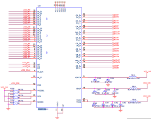
Could you pleases help to review the sechemetic of DS90C189-Q1, just for CMS application.

thanks!

  • Howdy!

    Some of the capacitors connected to the different VDD outputs are missing/do not have the correct values according to the EVM User Guide.
        - Connected to the VDDTX pin, there should be one 10uF cap, one 1uF cap, and two 0.1uF caps all in parallel
        - Connected to the VDDP pin, cap C357 should be 1uF instead of 0.01uF. In addition to this, this pin is missing an extra 0.1uF cap in parallel.
        - Connected to the VDD1 and VDD2 pins, there should be three 0.1uF caps, one 1uF cap, and one 10uF cap all in parallel. Your current configuration seems to be missing a cap and the values are off.

    Your PDB pin does not seem to be connected to either a pull up resistor or a grounded cap. This, is needed to ensure that PDB is not powered high before VDD is high. For example, a 1k Ohm resistor could be connected between VDD and the PDB input and a 10uF cap could be connected between the PDB input and ground For reference on the PDB power up sequence, please see figure 7-6 in this device's datasheet.

    Additionally, your VODSEL, RFB, and MODE0 pins should be connected to a 10uF cap between their inputs and ground as well.

    Lastly, it looks like one of your RGB inputs is mapped to the wrong pin as In_27 is left open. For the color inputs, there should be 25 total bits: 24 bits for color and 1 bit for a general purpose or L/R control bit.

    This device's EVM User Guide has additional information on schematics, but if you have any other questions, please let me know.

    Best,

    Cameron Carlson