This thread has been locked.

If you have a related question, please click the "Ask a related question" button in the top right corner. The newly created question will be automatically linked to this question.

TL16C752C: A parity error is happened when TL16C752B is replace with TL16C752C.

Part Number: TL16C752C


Hello guys.

One of my customers uses TL16C752B for their current products using their stock of the device.
But the stock will be run out in a few months. So they are evaluating TL16C752C for TL16C752B replacing.

In the evaluation. a parity error was happened under following conditions.
Could you please give me your reply or any counter measure?
Q.
We are evaluating TL16C752C on current production board for TL16C752B replacing.
At that time, a parity error was happened when data was received continuously.
Operating conditions are below.
Input clock 19.6608MHz, 4800bps, data 7bit, even parity, stop bit1.

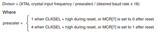
When the internal divisor value for baud rate setting is -1 from the current value,
the parity error was resolved and the sent data from external was received correctly.

Our questions are the follows.
1. Is the countermeasure (decrement 1 from current divisor value) correct?
2. Why was the parity error happened?
3. Was there any similar case in past?

When the baud rate was changed to 9600bps case, the parity error was solved without the countermeasure above.

Your reply would be much appreciated.

Best regards,
Kazuya.

  • HI Kazuya,

    Question on the TL16C752B from my end. Did the customer evaluate the "B" version of the device and get it working? When the customer switched over to the "C" version, errors occurred?

    At that time, a parity error was happened when data was received continuously.

    Does this statement change if data is intermittent? Does the fact that data is received continuously rather than in byte sizes affect if the data was received correctly without parity error? 

    1. Is the countermeasure (decrement 1 from current divisor value) correct?

    Input clock = 19.6608 MHz

    Desired Baud Rate = 4800bps

    Assuming MCR[7] = 0, prescaler = 1

    Using the equation from the datasheet: 

    Divisor = (19.6608MHz / 1) / (4800 x 16) = 256

    DLL and DLH registers need to be programmed in order to generate correct baud rate. 

    DLL = 0xFF = b11111111

    DLH = 0x00 = b00000000

    May we check with the customer to read DLL and DLH registers to see if these divisor registers were set correctly? 

    Decrement 1 from the current divisor value might work because the division was slightly off, or maybe there is some variation in the input clock crystal. It may not be exactly 19.6608MHz, so reducing the devisor could potentially fix the issue. 

    TL16C752C does have a short-stop bit errata. For example, if baud rate is 9600, then the length of a single stop bit is 104us. If the transmitter sends a stop bit of 98uS duration, this could make the TL16C752C miss a subsequent start bit. 

    To fix this, try having the customer change the number of stop bits from 1 to 1.5 or 2 stop bits. See if changing the # of stop bits fixes the issue with decrementing the divisor by -1. 

    2. Why was the parity error happened?

    Parity error happens when the transmitters sends a data byte that is not received correctly by the receiver. So parity error checks for atleast 1 corrupted bit in a data transfer. 

    3. Was there any similar case in past?

    I have not seen a similar case in the past. 

    When the baud rate was changed to 9600bps case, the parity error was solved without the countermeasure above.

    Not sure why increasing the speed fixes the issue. Maybe a scope capture of the data lines at 4800bps and 9800bps might be of some use here to analyze the issue. 

    Regards,

    Tyler

  • Hi Tyler,

    Thank you very much for your reply.
    I reply you as the follows.

    Your Question1: Did the customer evaluate the "B" version of the device and get it working?
                               When the customer switched over to the "C" version, errors occurred?

    -> The communication was no problem in "B" version case.
        When the customer switched over to the "C" version, errors occurred. But the customer switched RS232C driver at same time.
        And they didn't change any controller program in both case. 

    Your Question2: It may not be exactly 19.6608MHz, so reducing the devisor could potentially fix the issue.

    ->The clock was 19.6608MHz exactly. The clock is generated from crystal oscillator.

    Your question3: Try having the customer change the number of stop bits from 1 to 1.5 or 2 stop bits.
                              See if changing the # of stop bits fixes the issue with decrementing the divisor by -1. 

    -> They will confirm it in a few days.

    1. Their DLH/DLL register value was difference from you wrote.
        Your setting:   DLH = 0x00 = b00000000, DLL = 0xFF = b11111111
        Their setting:  DLH = 0x01 = b00000001, DLL = 0x00 = b00000000
        At this point, they have a question.

       Q. We can understand that divisor must be 256. But we can't understand the divisor registers should DLH = 0x00, DLL = 0xFF.
           It is 255d not 256d. Why do we need to set 255d for 256 divisor? Is there any explanation in the device datasheet?

    Could you give me your reply?

    Thank you again and best regards,
    Kazuya.
      

  • Hi Kazuya,

    The communication was no problem in "B" version case.
        When the customer switched over to the "C" version, errors occurred. But the customer switched RS232C driver at same time.
        And they didn't change any controller program in both case. 

    I was double checking to see if the changing to the "C" version was the issue, but since RS232C driver changed at the same time, we can't be so sure that the "C" version is the culprit. 

    ->The clock was 19.6608MHz exactly. The clock is generated from crystal oscillator.

    How was this measured? 

       Q. We can understand that divisor must be 256. But we can't understand the divisor registers should DLH = 0x00, DLL = 0xFF.
           It is 255d not 256d. Why do we need to set 255d for 256 divisor? Is there any explanation in the device datasheet?

    Mis-calculation on my end. Set DLH = 0x01 and DLL = 0x00. 100hex = 256 dec, so their divisor is correct. 

    Waiting on customer findings from increasing the length of the stop bit. It would be interesting to confirm this with some scope captures as well.

    Regards,

    Tyler