This thread has been locked.

If you have a related question, please click the "Ask a related question" button in the top right corner. The newly created question will be automatically linked to this question.

DP83826E: Configuration using MDIO, not hardware strap settings

Part Number: DP83826E
Other Parts Discussed in Thread: ASH, DP83826I,

Hi,
I am looking to configure DP83826E using MDIO interface (from Linux host/mdio-tools), and not strap pins.

I can set speed, auto-negotiate this way by writing to 0x0 (BMCR) register - though can't seem to find how
to set "RMII master mode" (without setting Strap4 pin high) in Basic mode? Please advise.

Is there some doc/note that explains where (which register bits) strap pins sampled at reset are recorded?
Thinking perhaps that might shed light on how to bypass strap pins and write config exclusively via MDIO.

Thanks for your timely attention and help.

  • Hi Ash,

    You can use Register 0x17 bit 5 to enable RMII. Setting this bit to 1 should enable RMII Master mode.

    Register 0x468 gives you the straps sampled at reset.

    --
    Regards,
    Gokul.

  • Thanks Gokul,

    I tried setting bit 5 to 1 in register 0x17, for RMII Master mode, but looking at RX_CLK/50MHz_RMII pin 
    (#19) - which at 100 Mbps speed setting, should have been outputting 50 MHz clock, right? But it's still
    outputting 2.5 MHz as before (sounds like still left in MII, 10 Mbps default mode?)  DP83826 datasheet 
    reg 0x17, bit 5 description reads "Reserved". Hope I am using it correctly to set RMII Master mode.
     
    I sent you more information, along with schematic so you have better context for the issue/s I am facing.
    Could you please review those and reply back as soon as you can. Will appreciate your timely attention
    and help please.

    Best,
    Ash

  • Hi Ash,

    Looks like the bit 5 is left reserved because of a mistake from our side. We are planning to add it in the next version of datasheet.

    After setting bit 5 to '1', can you please confirm that the value read back value of register 0x17 is 0x61?

    Can you also try programming a soft reset after programming reg0x17? You will have to program 0x017 = 0x61 followed by 0x1F = 0x4000.

    --
    Regards,
    Gokul.

  • Thanks Gokul,

    That worked:) Now I am moving on to testing Enhanced mode. Two questions/ clarifications needed in that connection: 

    I am referring to datasheet - "DP83826E, DP83826I | SNLS647F – DECEMBER 2019 – REVISED NOVEMBER 2022"
    1) 
    Note at the bottom of page 50 reads "This strap is latched at POR only. HW reset using pin or register will not re-latch
    this strap."
    Does this note apply only to Strap1 - or other straps too (which ones)?

    2)
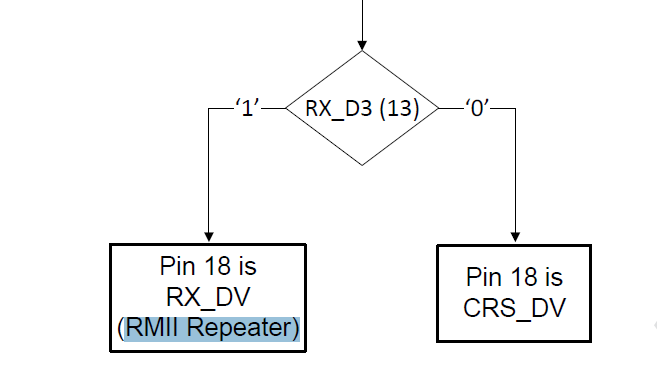
    Figure 9-11. Enhanced Bootstrap Flowchart shows Strap7 to control Pin18 as CRS_DV(RMII Repeater) when '0', and 
    RX_DV when '1'.
    On the next page Table 9-10.RMII MAC Mode Strap Table shows 0 RMII_CRS_DV, 1 RMII_RX_DV (for RMII repeater
    mode).
    I think the two pin function names seem to match - so is it just the 'RMII repeater mode' label that's misplaced maybe?

    Please advise.

    Best,
    Ash

  • Hi Ash,

    Please find my comments below.

    Does this note apply only to Strap1 - or other straps too (which ones)?

    It is only valid for Strap1.

    I think the two pin function names seem to match - so is it just the 'RMII repeater mode' label that's misplaced maybe?

    You are correct, the label RMII repeater mode is misplaced. Please find below correct mapping.

    --
    Regards,
    Gokul.

  • Thanks Gokul,

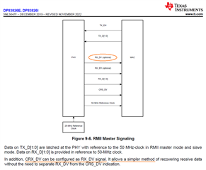
    Referring to DP83826E datasheet/ Figure 9-6. - my implementation is using RMII Master
    configuration. In that case Strap7 should be left at default (0) low state - which combines
    RX_DV and CRS_DV functions on one signal (on Pin 18), right?
    Following current datasheet/ Figure 9-11. Enhanced Bootstrap Flowchart, I have a 2.49K
    pullup on pin13/ Strap7 - is there a way to change this setting using MDIO register? If so, 
    which register and bit I should change (to 0, overriding strap7 pin setting in H/w)?

    What will happen if I set Strap7 high (pulled up to VDDIO) - will the Phy chip misbehave; 
    due to missing receive validation? I ask since RX_DV is shown as a separate, "optional"
    signal -- which (don't know which pin this optional RX_DV will use) I'm not using it in my
    design?

    Please advise.

    Best,
    Ash

  • Hello Ash,

    I have to check if there is a register to control CRS_DV and RX_DV. I will check this with my team and get back to you.

    What will happen if I set Strap7 high (pulled up to VDDIO) - will the Phy chip misbehave; 
    due to missing receive validation?

    The CRS_DV signal is an output for the PHY and the performance on the PHY is not impacted even if this pin is RX_DV. It is the MAC which takes this signal as input.
    I would expect that the MAC/Host will misbehave. You'll have to check with the MAC vendor to confirm this.

    --
    Regards,
    Gokul.

  • Hi Gokul,

    Any update on register access/ details to control CRS_DV and RX_DV?

    In the meantime - I removed the 2.49K pullup from pin13 (Strap7) since 
    we want CRS_DV (not RX_DV) for this non-repeater configuration - not 
    sure if that's the reason behind it or not but seems like with that change 
    the speed of packet exchanges are getting a bit slower. Will investigate 
    further if that's in fact the case or there's some other factor to slowness.

    Best,
    Ash

  • Hello Ash,

    Sorry, I couldn't get those details yet. I reached out to my team and I'll try to get those details by tomorrow.

    Ethernet is just a transceiver and doesn't stop or buffer any packets. Unless there are packet errors or the speed of transmission is 10M, slowness of packet exchanges might not be caused by DP83826.

    --
    Regards,
    Gokul.

  • Hi Ash,

    You can use register 0x0302[8] to switch between RX_DV and CRS_DV.

    --
    Regards,
    Gokul.

  • Thanks Gokul,

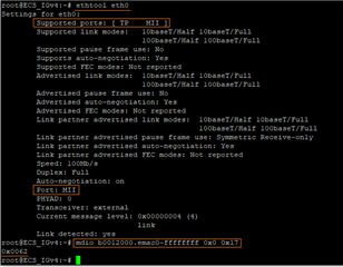
    mdio-tool is limited to accessing registers 0-31 -- but I have Strap 7 left open (no pull-up).
    However the ethernet link is functioning - when I use ethtool (please see output attached)
    it seems to think the port is MII (not RMII). Is there a way to double-check DP83826 is set 
    to RMII?


    Best,
    Ash

  • Hi Ash,

    I am not sure how ethtool decides if the port is in MII or RMII.

    Can you please probe Pin 19 (RX_CLK/50MHz_RMII) and check is you can see 50MHz clock?

    --
    Regards,
    Gokul.

  • Thanks Gokul,

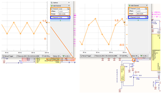
    Please see attached - (50MHz clock) waveform as seen/ probed on Pin 19 (RX_CLK/50MHz_RMII) and, 
    also for your reference, including 25MHz oscillator output waveform, captured at XO (Pin 8 of dp83826).
    Please review and advise whether or not (both of) these waveforms look good(?)

    FYI, Ethernet PHY section of my design schematic (including XTAL1 part#) is identical to DP83826EVM 
    (HSDC077, Rev: A)

    Best,

    Ash

  • Hello Ash,

    I am not sure what kind of oscilloscope you are using and why the number of samples used are very low.

    At least it looks like there is 50MHz signal on RX_D3, which means that the device is configured in RMII mode correctly.

    --
    Regards,
    Gokul.