Part Number: DP83826E
Hi there, I am referencing article https://e2e.ti.com/support/interface-group/interface/f/interface-forum/1171778/dp83826e-leds-in-basicmode-contimued?tisearch=e2e-sitesearch&keymatch=DP83826E#
As there seems to be a conflict between the "Accepted Answer" noted there, the datasheet, and the EVM module schematics.
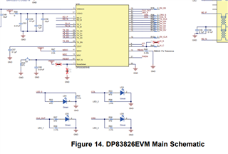
The "Accepted Answer" noted in the thread above does not in fact agree with the datasheet or EVM module schematics as shown in the screenshot below.
In the EVM module, it appears that, in fact, the LEDs do not require VCC pullup in order to function and that the LEDs are driven directly via GPIO of the DP83826E.
I think this really should be made more clear in the documentation and anyone who comes across the other thread. I was unable to find any info of sourcing current in the documentation either. It seems like an oversight in the datasheet to clearly spec if this GPIO (for LEDs) is sink/source open drain and/or sourcing/sinking electrical characteristics. Only info provided is recommendation to bootstrap which remains unclear.
I'd like some design support on this to clarify the correct implementation to avoid overdriving the LED pins.
TI EVM module screenshot source: www.ti.com/.../snlu262.pdf