This thread has been locked.

If you have a related question, please click the "Ask a related question" button in the top right corner. The newly created question will be automatically linked to this question.

TCA9517: How to use TCA9517 Star connection for B port.

Part Number: TCA9517
Other Parts Discussed in Thread: TCA9800, PCA9306, , TCA9555, TCA9509

I received a request from the designer of equipment by June 21st. 
please follow.

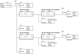
PDF is block Diagram.
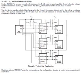
Is it use TCA9517 (TCA9517DGKR) in star configuration for B port? In the following excerpt from the datasheet,  Although the A port side is star-connected.     Is it possible to make a star connection on the B port side? Please let me know if there are any points to note in that case.
* There is concerned about the following sentence in the last line.
"Multiple A sides of TCA9517 s can be connected in a star configuration, allowing all nodes to communicate with each other."

・TCA9517 DataSheet
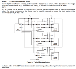
 [10.2.2.2 VILC and Pullup Resistor Sizing]
  

Condition of use
- SDA1, SCL1 side of the voltage translator connect 1.8V.
- other 3.3V above.
-- It is concerned about the design.
Is it possible to star connect the B port side of the TCA9517 (TCA9517DGKR)? If possible, are there any precautions for use? If it is not possible, the B port will be connected to the SLAVE side,
resulting in a situation where there is almost no low side margin (margin less) for the VIL regulation of the device under the TCA9517 (TCA9517DGKR).
Please advice 
recommended circuit configuration  or Other part number.

I2C_block_diagram.pdf
Thank you, Best Regards,
Katsumi
  • Section 9.3.3 of the datasheet says:

    This type of design prevents 2 B-side ports from being connected to each other.

    You need to exchange the A/B sides.

    I would recommend the TCA9800/1/2/3, which uses a different architecture with very low VOL on both sides. It has no voltage offset, but a current source, which implies that there must no external pull-ups on its B side. (This implies that you cannot use the PCA9306 on the B side; those translators also should be TCA980x.) Like the TCA9517, multiple B sides must not be connected together.

  • Hey Katsumi,

    In addition to Clemens' response, please also see the TCA9509 that allows the B-sides to be configured in a star application. Note that this is acceptable since the SVO is now on the A side, instead of the SVO on B-side that TCA9517 has.

    Regards,

    Jack 

  • Thank your for your kindness opinion, Clemens Ladisch san , Jack Guan san.

    Thank you for suggesting a solution from the datasheet and block diagram.
    I considered the configuration diagram with TCA9509, other PCA9306 and TCA9555.
    In addition, I have questions.

    Update PDF.
    File attached: I2C_Block_Diagram_2.pdf

    2 Questions:
    1) A-Side of TCA9509 recognized that pull-up resistance is unnecessary.
    Is it my recognaize correct?

    2) Is it the pull-up resistance between the PCA9306 and the TCA9555 connection?

    thank you.
    Best regards,
    Katsumi

    I2C_Block_Diagram_2.pdf

  • Thank your for answer.
    In Additional question.

    What does means A-side and B-side [The SVO].

    example) TCA9517 figure


    Thank you
    Best regards,
    Katsumi

  • Hey Katsumi,

    I have modified the block diagram you have sent over to be more accurate: 

    1.) Swapping the A and B sides of the TCA9517 so the star configuration can be performed.

    2.) PCA9306 is replaced by TCA9509. The reason being that the VOL of TCA9517 on B-side is 0.53V. After this logic low propagates through the PCA9306, it will rise closer to your maximum VIL of <=0.63V, which brings you closer to the ceiling of VIL max. 

    3.) The 2kohm pullup can now be removed on the A-side of the TCA9509 in place of the PCA9306. 

    1) A-Side of TCA9509 recognized that pull-up resistance is unnecessary.
    Is it my recognaize correct?

    Yes your understanding is correct. Since the static voltage offset (SVO) is on the A-side, the pullups on A-side should also be removed.

    The SVO characteristic helps the device realize which side of the device is driving a logic low whilst preventing a potential I2C bus lockup when a logic low is propagated. The TCA9517 utilizes it on the B-side, whereas the TCA9509 utilizes it on the A-side. 

    Let us know if you have any further questions/ concerns. 

    Regards,
    Jack 

  • Thank you for your suggestion about the circuit.
    I reviewed the design and was able to FIX the circuit.
    I'm really thankful to you.
    Best Regards,
    katsumi