This thread has been locked.

If you have a related question, please click the "Ask a related question" button in the top right corner. The newly created question will be automatically linked to this question.

TCAN4551-Q1: TCAN4551-Q1 - SW support

Part Number: TCAN4551-Q1

Hello,

We are using TCAN4551 CAN FD transceiver in our design. We need the transceiver to enter into sleep mode during Undervoltage. We are following the below steps.

INT - disabled

MO - 00 (Sleep mode via SPI command)

But the transceiver remains in the standby mode. Can you please help us with this issue?

  • Hello Swathi,

    I don't quite understand the sequence of events between placing the device into Sleep mode and the Undervoltage event.  The device was designed to power up or return to Standby Mode after recovering from an Undervoltage event.

    Can you provide me with more information about the voltage sequencing and what is causing the undervoltage?  Typically the voltage should not drop down below the undervoltage thresholds during normal operation and if it does, the device should recover to a protected state, which in the case of the TCAN4551 is Standby Mode.

    Regards,

    Jonathan

  • Hi Jonathan,

    I'm trying to put my transceiver to sleep in the case of removal of my external wake up signal. We are having a separate external wake up circuit in our system that controls the main regulator. But the transceiver always goes to the standby mode without entering the sleep mode. Also, My MCAN_INT1 is always at logic 1.

  • Hello Swathi,

    Can you please provide some additional information on the voltage levels of the VSUP during all of this?  Is this controlled by the "main regulator" you mentioned, or does that regulator only provide the lower VIO voltage (1.8V, 3.3V, or 5V)?

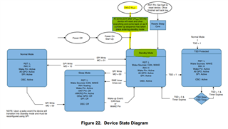
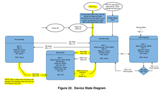
    As can be seen in the Device State Diagram, an UVLO on VSUP will cause the device to automatically re-enter Standby Mode when the UVLO voltage has recovered.  This also occurs during the initial Power On or a Power On Reset (POR) event.  This is why I am asking for you to pleases provide the voltage and power sequencing so that we can determine if the voltage is causing the device to re-enter Standby Mode.

    The VSUP voltage should not be removed or fall below the UVLO threshold while the device is in Sleep Mode and VSUP is intended to always be ON. See section 8.4.6.6 of the TCAN4551-Q1 datasheet for a detailed explanation of the UVLO behavior.

    The Device State Diagram also shows that setting MO=0 will cause the device to enter Sleep Mode. However, it may be possible that the device is immediately seeing a wake event which causes it to transition back to Standby Mode.

    There are a couple of wake event options you can check for.  The first two are:

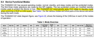
    • CAN bus activity will cause a Wake Up Pattern (WUP) and wake up the device causing it to transition to standby mode. See section 8.4.3.1 of the TCAN4551-Q1 datasheet for a detailed explanation of a Bus Wake Up via WUP.
      • There should not be activity on the CAN bus while the device is in Sleep Mode, otherwise this activity will likely satisfy the requirements for a WUP and cause the device to wake up and enter Standby Mode.
    • A Local Wake Up (LWU) event which is a edge transition on the WAKE pin will cause the device to transition to standby mode. See section 8.4.3.2 of the TCAN4551-Q1 datasheet for a detailed explanation of a Wake Up via LWU.
      • You can disable the LWU by setting WAKE_CONFIG=00 (Register 0x0800[31:30])

    The other option is:

    If the device is in sleep mode and reset is toggled the device enters standby mode and at that time INH and nWKRQ turns on. Therefore, you should not pulse the Reset (RST) pin while in sleep mode to prevent the device from transitioning to standby mode.

    Also, My MCAN_INT1 is always at logic 1.

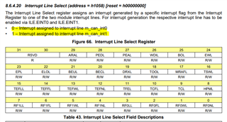
    There are two MCAN Interrupt Lines that that you can use to assign the different interrupt bits to.  This allows you to separate higher priority interrupt events to a particular interrupt line to the MCU and lower priority interrupt events to a different interrupt line.  The MCU's Interrupt Service Routine (ISR) could then be configured to service the higher priority interrupts before the lower priority events if both lines had interrupt bits set.  By default, all interrupts are assigned to the MCAN_INT0, so you likely have not configured any interrupts to be represented on MCAN_INT1 which is why it is always logic 1.

    Regards,

    Jonathan

  • Hi Jonathan,

    Please find the required details below.

    1. The main regulator is only controlling the VIO (3.3V). VSUP is always present (13.5V).

  • Hi Swathi,

    Thank you for the confirmation on the power.  If VSUP is always present, then it should not receive a UVLO condition while you are trying to enter sleep mode and one of the other factors I have mentioned must be preventing the device from entering or remaining in sleep mode.  Can you verify that there is no CAN bus activity, the Reset (RST) and WAKE pins do not change state during or after you try to place the device into Sleep Mode?

    Regards,

    Jonathan