Hi team,
Here is an issue from the customer. According to the customer, now the customers have produced 50 circuit boards, and 8 of them are 100% sure to reproduce this issue.
Here are some details about this issue.
1. When the chip DC boost is configured as 80mV and AC boost is 3, some USB hosts will report USB error -71 and -110. From the fault log, it may be that the device descriptor failed to be obtained during the USB handshake phase, or the host failed to transfer to the device firmware after the successful handshake; under this configuration, ENA_HS 27K is pulled up, and EQ is suspended;
2.But we configure the dc boost as 60mV and AC boost as 3 on TUSB212 ,the USB host that originally reported the error returned to normal; Under this configuration, both ENA_HS and EQ are floating;
3. When the DC boost configuration is 80mV and the AC boost is 3, the test level of the TX SOF packet on the host side is only about 512mV, the disconnect threshold of the host is set to 677mV, and there is no disconnect sign in the log, and the TX of the host is initially excluded. SOF detection problem;
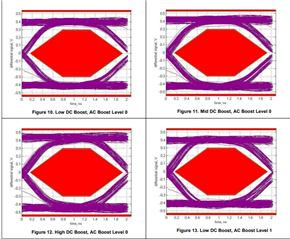
4.Under the two configurations, the eye diagram test meets the requirements, and there is no obvious difference;
Here are the questions:
Q1.For this issue, the customer want to know why the handshake and transmission of the USB link will return to normal and no error will be reported when the dc boost is reduced;
Q2. Could you please show more details that how the DC boost works?
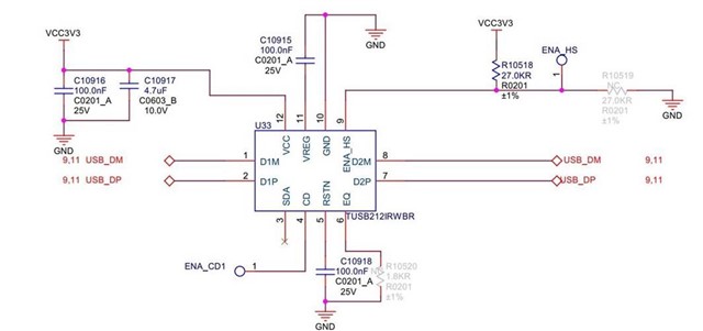
Q3 Could you please help me review this schematic?
The schematic diagram is as follows:
YOURS
NAN