This thread has been locked.

If you have a related question, please click the "Ask a related question" button in the top right corner. The newly created question will be automatically linked to this question.

DS90UB953-Q1: DS90UB953-Q1: setting pattern generator

Part Number: DS90UB953-Q1
Other Parts Discussed in Thread: ALP

Hi,

We have a system which includes a camera with the 953 serializer, connected via cable to a setup with the 960 deserializer driving a GPU.

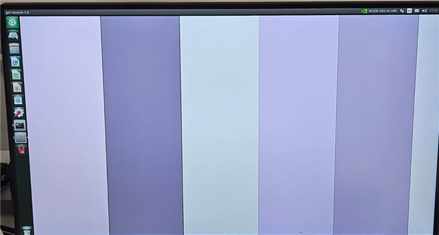
In nomal operation we can see the images from the camera as received by the GPU, however when we try to set pattern generation for the 953

serializer, there is no image displayed.

We have used the code example as shown in section 7.6.4 in 953 datasheet.

Do we need to set anything in the 960 different from the normal operation configuration?

Regards

  • Hi,

    We have tried setting pattern in RAW 12 mode, using another thread on this forum (linux-ds90ub953-q1-help-about-pattern-generation-of-ds90ub953) and we were able to see image, although resulting color bar is not as expected (colouring is pinkish...) 

    So now there are 2 questions - (1) what is the reason that the example described in section 7.6.4 in datasheet didn't result in image,

                                                      (2) what is the reason we do not get the colors in color bar

    Regards,

  • Hello,

    Thank you for your questions. Additional configurations should not be necessary on the 960 to receive data from the 953s pattern generator. Is your GPU programmed to receive a specific data type? The code example in the datasheet results in a 1920x1080 with 30fps and RGB888 data type. It's possible that your GPU may not be able to receive this data type/resolution, but is able to receive the data type/resolution of  your camera. Similarly, the RAW12 data may not be entirely recognizable/usable by the GPU, which is why you see unexpected data instead of no data at all. Could you double check the GPU and/or camera settings for any specific data type or resolution requirements?

    Regards,
    Darrah

  • Hi,

    Thanks for reply.

    Camera supports 1920x1080, up to 60 fps but we use 30fps at the moment.

    GPU is also supports this resolution but we also checked at lower resolution (1280x1080, 30 fps).

    For the 1920x1080, 30 fps, we got the the color bars with a pink background as shown below:

    The code we used (for RAW12, 1920x1080, 30 fps, 8 bars)

    board.WriteReg(0xB0, 0x00) # Indirect Pattern Gen Registers
    board.WriteReg(0xB1, 0x01) # PGEN_CTL
    board.WriteReg(0xB2, 0x01)

    board.WriteReg(0xB1, 0x02) # PGEN_CFG
    board.WriteReg(0xB2, 0x33) # NUM_CBARS, Block_size

    board.WriteReg(0xB1, 0x03) # PGEN_CSI_DI
    board.WriteReg(0xB2, 0x2C) # RAW12 Data Type

    board.WriteReg(0xB1, 0x04) # PGEN_LINE_SIZE1: 1920*12/8=2880
    board.WriteReg(0xB2, 0x0B)

    board.WriteReg(0xB1, 0x05) # PGEN_LINE_SIZE0: 1920*12/8=2880
    board.WriteReg(0xB2, 0x40)

    board.WriteReg(0xB1, 0x06) # PGEN_BAR_SIZE1: 1920*12/8/8)=360
    board.WriteReg(0xB2, 0x01)

    board.WriteReg(0xB1, 0x07) # PGEN_BAR_SIZE0: 1920*12/8/8)=360
    board.WriteReg(0xB2, 0x68)

    board.WriteReg(0xB1, 0x08) # PGEN_ACT_LPF1: 1080
    board.WriteReg(0xB2, 0x04)

    board.WriteReg(0xB1, 0x09) # PGEN_ACT_LPF0: 1080
    board.WriteReg(0xB2, 0x38)

    board.WriteReg(0xB1, 0x0a) # PGEN_TOT_LPF1: 1125
    board.WriteReg(0xB2, 0x04)

    board.WriteReg(0xB1, 0x0b) # PGEN_TOT_LPF0: 1125
    board.WriteReg(0xB2, 0x65)

    board.WriteReg(0xB1, 0x0c) # PGEN_LINE_PD1:1/(30*1125*10ns)=2963
    board.WriteReg(0xB2, 0x0B)

    board.WriteReg(0xB1, 0x0d) # PGEN_LINE_PD0:1/(30*1125*10ns)=2963
    board.WriteReg(0xB2, 0x93)

    board.WriteReg(0xB1, 0x0E) # PGEN_VBP: 33
    board.WriteReg(0xB2, 0x21)

    board.WriteReg(0xB1, 0x0F) # PGEN_VFP: 10
    board.WriteReg(0xB2, 0x0A)

    Later we changed for RAW12, 1280x1080, 30 fps, 8 bars, and while number of displayed bars is now 8, the bars colors are similar to the image attached.

    The code we used:

    board.WriteReg(0xB1, 0x04) # PGEN_LINE_SIZE1: 1280*12/8=1920
    board.WriteReg(0xB2, 0x07)

    board.WriteReg(0xB1, 0x05) # PGEN_LINE_SIZE0: 1280*12/8=1920
    board.WriteReg(0xB2, 0x80)

    board.WriteReg(0xB1, 0x06) # PGEN_BAR_SIZE1: 1280*12/8/8)=240
    board.WriteReg(0xB2, 0x00)

    board.WriteReg(0xB1, 0x07) # PGEN_BAR_SIZE0: 1280*12/8/8)=240
    board.WriteReg(0xB2, 0xF0)

    We suspect some mismatch in the programming of the pattern generator.

    Could you please advise?

    An additional question - we see that RGB888 mode is currently not successful when we use the datasheet example, is there another color bar mode recommended?

    Best Regards,

  • Hello,

    Thanks for providing the code that you are using. I'll review the settings to make sure all of the parameters are calculated correctly. Just to confirm that I have the correct parameters, are the blanking parameters for your system 33 lines for vertical back porch, 10 lines for vertical front porch, and 2 lines for sync? I'll have feedback on your code by Monday.

    The RGB888 in the datasheet example is referring to the CSI data type being used and is not necessarily a mode, but the pattern generator of the devices can use other CSI data types as well. If I'm misunderstanding your additional question though, please let me know.

  • Thank you so much

    Best Regards,

  • Hello,

    There does not appear to be any issues with your code based on the parameters you specified. Based on the image it looks like this may be more of an interpretation issue instead of a pattern generator code issue. Is the CSI receiver set up for a specific color mode? Is the CSI receiver expecting anything specific in a software sense? Can you try generating the pattern generator from within the Analog launch pad instead of setting registers through a pre-written script? This will help ensure that the pattern generator is programmed correctly. Is the same result seen for the pattern generator if it comes from both the serializer and the deserializer? 

  • Thank you for feedback.

    A few follow-up questions:

    a) >> .. Is the CSI receiver set up for a specific color mode? Is the CSI receiver expecting anything specific in a software sense?

    [AM] We will explore this further.

    b) >> generating from within the Analog launch pad -- [AM] Unfortunately we don't have one.

    c) >> Is the same result seen for the pattern generator if it comes from both the serializer and the deserializer?

    [AM] What is required to set this in the deserializer, beyond the similar register settings used for serializer?

    Thanks and Best Regards

  • Hello,

    a) Thanks for looking into the CSI receiver details. 

    b) Do you mean you don't have the equipment to interface with ALP or you don't have the ALP software available? Analog Launch Pad (ALP) is actually a free to download software developed for FPD-Link devices, which can be downloaded here, but if you don't have the equipment to interface with your board that is okay as well.

    c) Yes, the pattern generator in the derserializer is similar to the serializer and only involves register settings. Section 7.5.12 of the 960's datasheet contains all the details on the pattern generator, but the process is the same as the 953.

  • Hi,

    Thanks for the feedback and info.

    Best Regards

  • Hi,

    Another question - is there, by any chance, any screenshot available for a RAW12 pattern generator output image, at any resolution? (for reference)

    Best Regards,

  • Hello,

    Currently I do not have a screenshot for RAW12 available, but let me reach out to other members of the team to see if one may be available.

  • Hello,

    We unfortunately don't have a screenshot available to share. Have you made any progress on the CSI receiver's settings?