


Part Number: TCA9548A-Q1
Other Parts Discussed in Thread: TCA9548A
Hi, TI expert.
The customer is developing a charger cradle and has a question to confirm whether it is suitable for using the TCA9548A-Q1.
1. Part: TCA9548A-Q1
2. Application content: To read each data of the same slave address (There are about several I2C on the battery side, to read data separately)
3. Block Diagram
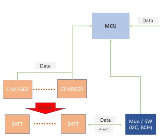
4. Inquiries
1) Is I2C communication per channel possible for the Slave address of the same address?
2) To read the battery information on Channel 1, put ‘1’ in B0 as shown below to transmit the data → After that, data bytes are sent and read. Is it right to proceed like this?
Please check. Thank you.
